


356485-UIM-G-1211
Johnson Controls Unitary Products 17
CATEGORY 1 - 450 F. MAX. VENT TEMP.
The venting system must be installed in accordance with Section 5.3,
Air for Combustion and Ventilation, of the National Fuel Gas Code
Z223.1/NFPA 54 (latest edition), or Sections 7.2, 7.3 or 7.4 of CSA
B149.1, National Gas and Propane Codes (latest edition) or applicable
provisions of the local building code and these instructions.
The furnace shall be connected to any type of B, BW or L vent connec-
tor, and shall be connected to a factory-built or masonry chimney. The
furnace shall not be connected to a chimney flue serving a sepa-
rate appliance designed to burn solid fuel.
It is recommended that the appliance is installed in a location where the
space temperature is 32 °F (0°C) or higher. If the appliance is installed
in a location where the ambient temperature is below 32 °F (0°C), the
combustion byproducts could condense causing damage to the appli-
ance heat exchanger.
This appliance may be common vented with another gas appliance for
residential installations as allowed by the codes and standards listed in
these instructions.
Non-HUD approved Modular Homes must be vented with an approved
roof jack and may not be common vented with other appliances.
VENTING
Category I venting consists of vertically venting one or more appliances
in B-vent or masonry chimney (as allowed), using single wall metal pipe
or B-vent connectors. Type B-vent system extends in a general vertical
direction and does not contain offsets exceeding 45°. A vent system
having not more than one 60° offset is permitted.
VENTING INTO AN EXISTING CHIMNEY
For Category I installations, the furnace shall be connected to a factory
built chimney or vent complying with a recognized standard, or a
masonry or concrete chimney lined with a material acceptable to the
authority having jurisdiction. Venting into an unlined masonry chimney
or concrete chimney is prohibited.
Where use of an existing chimney is unavoidable, the following rules
must be followed:
1. The masonry chimney must be built and installed in accordance
with nationally recognized building codes or standards and must
be lined with approved fire clay tile flue liners or other approved
liner material that will resist corrosion, softening, or cracking from
flue gases. THIS FURNACE IS NOT TO BE VENTED INTO AN
UNLINED MASONRY CHIMNEY.
2. This furnace must be vented into a fire clay tile lined masonry
chimney only if a source of dilution air is provided, such as by com-
mon venting with a draft hood equipped water heater. If no source
of dilution air is available, Type B vent must be used, or masonry
chimney vent kit 1CK0603 or 1CK0604 must be used. Refer to the
instructions with the kit to properly apply these masonry chimney
kits.
3. The chimney must extend at least 3 ft (0.91 m) above the highest
point where it passes through a roof of a building and at least two
feet higher than any portion of the building with a horizontal dis-
tance of ten feet.
4. The chimney must extend at least 5 ft (1.5 m) above the highest
equipment draft hood or flue collar.
FAN-ASSISTED COMBUSTION SYSTEM
This appliance is equipped with an integral mechanical means to either
draw products of combustion through the heat exchanger.
Ambient Combustion Air Supply
This type installation will draw the air required for combustion from
within the space surrounding the appliance and from areas or rooms
adjacent to the space surrounding the appliance. This may be from
within the space in a non-confined location or it may be brought into the
furnace area from outdoors through permanent openings or ducts. A
single, properly sized pipe from the furnace vent connector to the out-
doors must be provided. Combustion air is brought into the furnace
through the unit top panel opening.
An unconfined space is not less than 50 cu.ft (1.42 m
3
) per 1,000 Btu/
hr (0.2928 kW) input rating for all of the appliances installed in that
area.
Rooms communicating directly with the space containing the appli-
ances are considered part of the unconfined space, if doors are fur-
nished with openings or louvers.
A confined space is an area with less than 50 cu.ft (1.42 m
3
) per 1,000
Btu/hr (0.2928 kW) input rating for all of the appliances installed in that
area. The following must be considered to obtain proper air for combus-
tion and ventilation in confined spaces.
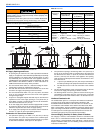
Combustion Air Source From Outdoors
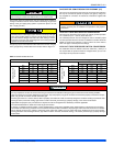
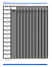
The blocking effects of louvers, grilles and screens must be given con-
sideration in calculating free area. If the free area of a specific louver or
grille is not known, refer to Table 7, to estimate free area.
* Do not use less than 1/4”(0.635 cm) mesh
+ Free area of louvers and grille varies widely; the installer should follow
louver or grille manufacturer’s instructions.
Dampers, Louvers and Grilles (Canada Only)
1. The free area of a supply air opening shall be calculated by sub-
tracting the blockage area of all fixed louvers grilles or screens
from the gross area of the opening.
2. Apertures in a fixed louver, a grille, or screen shall have no dimen-
sion smaller than 0.25” (0.64 cm).
3. A manually operated damper or manually adjustable louvers are
not permitted for use.
4. A automatically operated damper or automatically adjustable lou-
vers shall be interlocked so that the main burner cannot operate
unless either the damper or the louver is in the fully open position.
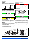
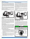
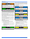
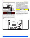
FIGURE 23: Combustion Airflow Path Through The Furnace Casing to
the Burner Compartment
This type of installation requires that the supply air to the appli-
ance(s) be of a sufficient amount to support all of the appliance(s)
in the area. Operation of a mechanical exhaust, such as an exhaust
fan, kitchen ventilation system, clothes dryer or fireplace may cre-
ate conditions requiring special attention to avoid unsatisfactory
operation of gas appliances. A venting problem or a lack of supply
air will result in a hazardous condition, which can cause the appli-
ance to soot and generate dangerous levels of CARBON MONOX-
IDE, which can lead to serious injury, property damage and / or
death.
Table 7: Estimated Free Area
Wood or Metal
Louvers or Grilles
Wood 20-25%*
Metal 60-70% *
Screens+
1/4” (0.635 cm)
mesh or larger 100%
Combustion Air