


15
IM-AS/02.00 GB (0412)
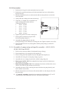
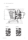
11.5.4 Assembly of pump casing and impeller assembly – AS 40, AS 50,
AS 60, AS 65 and AS 80
1. Fit the correct clearance shims (19) (adjusted from pre-fitting)
2. Fit the impeller key (11) and push on the impeller (3).
3. Fit the O-ring (16) in the impeller nut (10) and tighten the impeller (3).
4. Assemble the O-ring (13) in the pump casing (1) groove.
5. Assemble the cover casing (2) and lock it with the casing clamp (9).
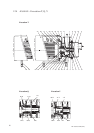
6. Motors up to size IEC 112. Fit the adjustable foot frame and lock it with the nuts
(30) and the screws (29).
7. Motor sizes larger than IEC 112. Fit the adjustable foot frame and fasten the screws
(29) for the front foot (20) and the rear foots (23).
8. Assemble the motor (50) by entering the motor shaft into the pump shaft (4) and
lock it with the screws (28).
9. Slide the shroud (44) over the motor (50) and assemble it on the adapter (43) with
the screws (46)
10. ‘‘V’’ and ‘‘Q’’ executions. Assemble the mechanical seal flushing pipes (71 and 71
respectively) on the mechanical seal cover ( 65 and 60 respectively).
A
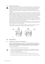
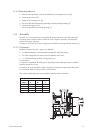
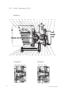
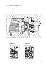
11.5.3.3 Q execution
1. Position the O-ring (61) on the mechanical seal cover (60).
2. Position the secondary stationary seal in the mechanical seal cover (60) and hex-
head screws (62).
3. Slide the mechanical seal cover (60) onto the shaft (4) and position it on the back
end of the shaft.
4. Gently slide the rotating seals onto the shaft (4).
5. Check the “A” length as it is essential for an
equal working load on both seal faces,
A measures as follows:
•AS 40 = 16.0mm
•AS 50 = 17.5mm
•AS 60 = 15.5mm
•AS 65 = 15.5mm
•AS 80 = 19.5 mm
6. Tighten the grub screws on the rotating seal.
7. Fit the primary stationary seal part in the
back of the pump casing (1).
8. Assemble the pump casing (1) onto the
bearing housing (5). Be careful not to damage the seal. Tighten with the screws (26).
9. Fit the mechanical seal cover (60) together with the pump casing (1) and lock it
with the (62).