


562156-UIM-A-0610
6 Johnson Controls Unitary Products
FIELD CONNECTIONS POWER WIRING
1. Install the proper size weatherproof disconnect switch outdoors and
within sight of the unit.
2. Remove the screws at the bottom of the corner cover. Slide corner
cover down and remove from unit. See Figure 5 "Typical Field Wir-
ing".
3. Run power wiring from the disconnect switch to the unit.
4. Remove the service access panel to gain access to the unit wiring.
Route wires from disconnect through power wiring opening provided
and into the unit control box.
5. Install the proper size time-delay fuses or circuit breaker, and make
the power supply connections.
FIELD CONNECTIONS CONTROL WIRING
(CONVENTIONAL)
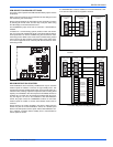
1. Route low voltage wiring into bottom of control box. Make low volt-
age wiring connections inside the junction box per Figures 10-12
“Thermostat Wiring”.
2. The complete connection diagram and schematic wiring label is
located on the inside surface of the unit service access panel.
3. Replace the corner cover and service access panel that were
removed in Steps 2 and 4 of the ”FIELD CONNECTIONS POWER
WIRING” section.
4. All field wiring to be in accordance with national electrical codes
(NEC) and/or local-city codes.
5. Mount the thermostat about 5 ft. above the floor, where it will be
exposed to normal room air circulation. Do not place it on an outside
wall or where it is exposed to the radiant effect from exposed glass
or appliances, drafts from outside doors, or supply air grilles.
6. Route the 24-volt control wiring (NEC Class 2) from the outdoor unit
to the indoor unit and thermostat.
FIELD CONNECTIONS CONTROL WIRING
(SERIAL COMMUNICATION)
1. The Communications Harness is provided with the Touch Screen
Communicating Control.
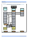
2. Route low voltage four conductor shielded thermostat communica-
tions harness into junction box and connect to communications port
on control board. See Figure 6 "Communications Harness Connec-
tion".
3. Route low voltage wiring into bottom of control box. Make low volt-
age wiring connections inside the junction box per Figures 8-9.
4. The complete connection diagram and schematic wiring label is
located on the inside surface of the unit service access panel.
5. Replace the corner cover and service access panel that were
removed in Steps 2 and 4 of the “Field Connections Power Wiring”
section.
6. Mount the thermostat about 5 ft. above the floor, where it will be
exposed to normal room air circulation. Do not place it on an outside
wall or where it is exposed to the radiant effect from exposed glass
or appliances, drafts from outside doors, or supply air grilles.
7. Route the 24-volt control wiring (NEC Class 2) from the outdoor unit
to the indoor unit and thermostat.
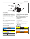
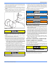
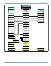
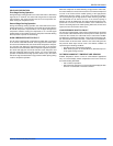
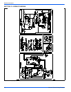
FIGURE 5: Typical Field Wiring
Ambient temperature sensor should extend below corner cover by
1”.
Corner
Cover
Control
Wiring
Power
Wiring
Service
Access
Panel
Ambient
Temperature
Sensor
NOTICE
To eliminate erratic operation, seal the hole in the wall at the ther-
mostat with permagum or equivalent to prevent air drafts affecting
the operation of the thermostat.
If unit is going to be setup as a communicating system, the conven-
tional wiring must be removed from the Outdoor Control Board, if
not, damage to control board or indoor control could occur.
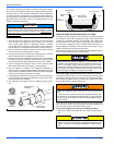
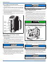
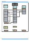
FIGURE 6: Communications Harness Connection
Ambient temperature sensor should extend below corner cover by
1”.
To eliminate erratic operation, seal the hole in the wall at the ther-
mostat with Pergamum or equivalent to prevent air drafts affecting
the operation of the thermostat.
NOTICE
COMMUNICATIONS PORT
CONTROL BOARD
COMMUNICATIONS
HARNESS
JUNCTION
BOX
NOTICE
NOTICE