


562156-UIM-A-0610
Johnson Controls Unitary Products 13
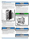
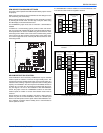
LED DIAGNOSTIC INDICATORS
The control includes two LED’s that display diagnostic information.
LED1 is red and LED2 is green. These LED’s are used to display oper-
ational mode, fault information. A third LED, LED3 is used to display
status information. LED3 is yellow. These LED’s are used to display
operational mode, status, and fault information.
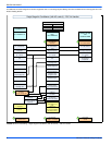
OPERATIONAL MODE DETECTION
The control can be used in a variety of applications including AC units
with multistage compressors. The control uses various inputs to deter-
mine the proper mode of operation.
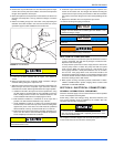
The control senses the connections that are made to M, M1, and M2
terminals and determines the correct operational mode for the control.
This is done each time power to the control is cycled. Therefore, it is
important that no loads be attached to the M1 or M2 terminals of the
control for single-stage compressors, and no loads be attached to the
M1 terminal of the control for a scroll two-stage compressor.
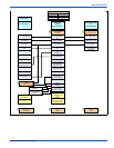
OPERATIONAL MODE DISPLAY
The control will display its active operational mode using the onboard
LED’s when the TEST pins are connected while no thermostat signals
are energized. Table 3 "Operational Mode Display" describes the oper-
ational modes. The control will display the operational mode as long as
the TEST pins are shorted and no thermostat signals are energized.
When the TEST pin short is removed, the control will return to normal
LED displays.
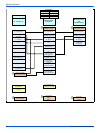
STATUS CODE DISPLAY
The control also provides status codes using the LED’s. Status codes
indicate the state of the operation of the unit but do not represent a
fault. Tables 4 & 5 describes the LED displays during status codes. Sta-
tus codes will not be displayed when a fault code is present.
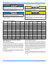
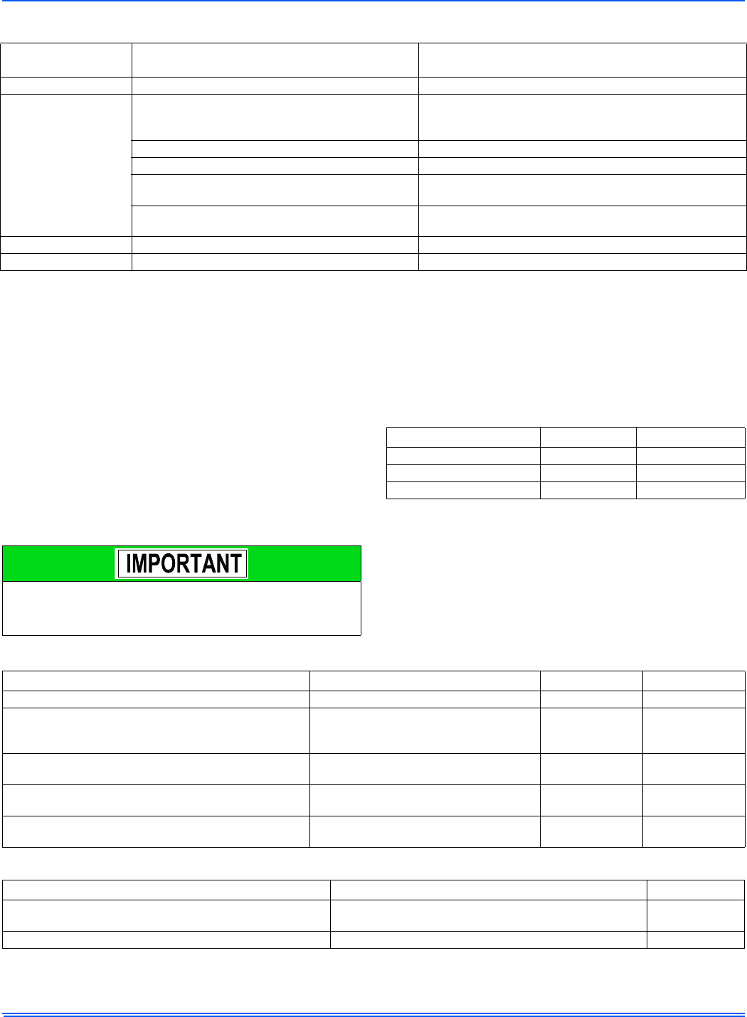
TABLE 2:
TEST Input Functionality
Duration of
connection (seconds)
Control Behavior with no system
master signals present
Control behavior with system
master signals present
< 2 No response No response
2 <
Display compressor type TS, Ultratech, or
single stage compressor, Ignore LPS
Bypass ASCD (Reduce timer to zero immediately).
If Y1 (thermostat or communication) is present and the
high-pressure switch is closed, contactors will be energized.
Clear soft lockout Clear soft lockout
Clear hard lockout Clear hard lockout
Reset TS anticipation mode counter
to zero for TS systems.
Reset TS anticipation mode counter
to zero for TS systems.
Reduce TS staging delays for TS
systems as described below.
Connection removed Resume normal LED display
Connection not removed Nothing more than previously explained
Do not connect any loads to the M1 or M2 terminals of the control
for single-stage compressors, and no loads should be attached to
the M1 terminal of the control for scroll two-stage compressor.
Incorrect system behavior could result.
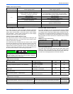
TABLE 3:
Operational Mode Display
Compressor Type LED1 (Red) LED2 (Green)
Single Stage Compressor 1 flash ---
TS Compressor 2 flashes ---
UltraTech Compressor 3 flashes ---
TABLE 4:
Status Code Display
Description Required Condition LED1 (Red) LED2 (Green)
No power to control No power to control OFF OFF
First-stage compressor operation – TS or UltraTech
TS – M & M1 energized,
UltraTech – M energized,
Single Stage - NA
OFF ON
Second-stage compressor operation - TS, UltraTech, or
Single Stage
TS and UltraTech – M & M2 energized,
Single Stage – M energized
ON ON
Control normal operation – no communication or call for
compressor present
No faults active, Y1 or Y2 not present OFF 2s ON / 2s OFF
Control normal operation – in ASCD period
No faults active, Y1 or Y2 present,
ASCD timer not expired
OFF
0.1 sec ON /
0.1 sec OFF
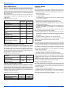
TABLE 5:
Status Code Display
Description Required Condition LED3 (Yellow)
Control normal operation – with active communication present System is active and presently communicating successfully.
0.1 sec ON /
0.1 sec OFF
Control powered – without active communication present System has 24 VAC present and the microprocessor is active. 2s ON / 2s OFF