872678-UIM-C-0213
6 Johnson Controls Unitary Products
SECTION VII: SYSTEM CHARGE
The factory charge in the outdoor unit includes enough charge for the
unit, a 15 ft. (4.6 m) line set, and the smallest indoor coil match-up.
Some indoor coil matches may require additional charge. See tabular
data sheet provided in unit literature packet for charge requirements.
The “TOTAL SYSTEM CHARGE” must be permanently stamped on the
unit data plate.
Total system charge is determined as follows:
1. Determine outdoor unit charge from tabular data sheet.
2. Determine indoor coil adjustment from tabular data sheet.
3. Calculate the line charge using the tabular data sheet if line length
is greater than 15 feet (4.6 m).
4. Total system charge = item 1 + item 2 + item 3.
5. Permanently stamp the unit data plate with the total amount of
refrigerant in the system.
Use the following charging method whenever additional refrigerant is
required for the system charge.
If a calibrated charging cylinder or accurate weighing device is avail-
able, add refrigerant accordingly. Otherwise, model-specific charging
charts are provided on the access panel of the unit.
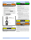
SUPERHEAT CHARGING METHOD -
PISTON INDOOR
1. Set the system running in cooling mode by setting the thermostat
at least 6°F below the room temperature and operate system for at
least 10 – 15 minutes.
2. Refer to the technical guide for the recommended airflow and ver-
ify indoor airflow (it should be about 400 SCFM per ton).
3. Measure and record the outdoor ambient (DB) temperature and
the suction pressure at the suction service valve.
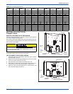
4. Using the charging chart located on the unit, find the intersection
of the outdoor ambient dry bulb and the suction pressure obtained
in step 3. This is the recommended suction tube temperature at
the service valve.
5. Measure and record the suction tube temperature at the service
valve and compare to the recommended temperature obtained in
step 4.
6. Add charge if the measured suction temperature in step 5 is above
the recommended value. Remove / recover refrigerant if the mea-
sured suction temperature is below the recommended value.
SUBCOOLING CHARGING METHOD - TXV INDOOR
For cooling operation, unless otherwise specified, the default subcool-
ing is 10°F.
1. Set the system running in cooling mode by setting the thermostat
at least 6°F below the room temperature and operate system for at
least 10 – 15 minutes.
2. Refer to the technical guide for the recommended indoor airflow
and verify it is correct (it should be about 400 SCFM per ton).
3. Measure and record the indoor wet bulb (WB) and the outdoor
ambient dry bulb (DB) temperature.
4. Using the charging chart located on the unit, find the intersection
of the indoor wet bulb and the outdoor dry bulb. This is the recom-
mended liquid pressure (and subcooling value).
5. Measure and record the pressure at the liquid valve pressure port
and compare to the value obtained in step 4.
6. Add charge if the measured liquid pressure is lower than the rec-
ommended value. Remove / recover charge if the measured liquid
pressure is above the recommended value.
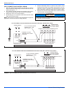
Condenser subcooling is obtained by calculating the difference of the
saturated refrigerant temperature of the pressure measured at the liquid
base valve and the liquid tube temperature as measured at the liquid
base valve.
Subcooling Temp. (TC) = Saturated Temp. (TS) – Liquid Temp. (T).
Do not leave the system open to the atmosphere.
DO NOT attempt to pump “Total System Charge” into outdoor unit
for maintenance, service, etc. This may cause damage to the com-
pressor and/or other components. the outdoor unit only has enough
volume for the factory charge, not the “Total System Charge”.
Refrigerant charging should only be carried out by a qualified air
conditioning contractor.
Compressor damage will occur if system is improperly charged. On
new system installations, charge system per tabular data sheet for
the matched coil and follow guidelines in this instruction.
Example: The suction tube temperature listed on the table at the
intersection of the outdoor DB and the suction pressure is 63°F.
Temperature of the suction tube at the service valve is 68°F. It would
be necessary to add refrigerant to drop the suction tube temperature
to 63°F.
Example: The liquid pressure listed at the intersection of the indoor
WB and the outdoor DB 320 psig. Pressure at the liquid valve is 305
psig. It would be necessary to add refrigerant to increase the liquid
pressure to 320 psig.
IT IS UNLAWFUL TO KNOWINGLY VENT, RELEASE OR DIS-
CHARGE REFRIGERANT INTO THE OPEN AIR DURING
REPAIR, SERVICE, MAINTENANCE OR THE FINAL DISPOSAL
OF THIS UNIT.


