


The enclosure recommendations listed are external dimensions which assume the use of 3/4” (19mm) thick material. If you are using 5/8” (16mm) thick material, subtract 1/4”
(6.5mm) from each dimension. Do not use any material with a thickness of less than 5/8” (16mm) as this may compromise the rigidity of the enclosure.
All enclosure volumes listed are net internal volumes! Box volume displacement, port displacement and brace displacement must be added to obtain the final gross internal
volume. All enclosure dimensions listed have already taken this into account.
JL AUDIO M10IB5/M10W5 3
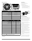
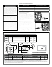
INTERCHANGEABLE LOGO BADGE
(Sport-Grille Models Only)
Interchangeable Logo Badges for Sport Grille
model subwoofers are included to further customize
your installation. The design of the Sport Grille allows
for the JL Audio logo to be added in your choice of
included colors and oriented in the manner that best
suits your installation.
NOTE: A left and a right badge of each color is
included. These two different orientations ensure
the “JL Audio” Logo will read correctly wherever
positioned (most commonly the 3:00 or 9:00
position).
Remove the adhesive backing from the badge
and affix the badge to the grille using the small
positioning hole as a guide. See diagram at right.
!!
CAUTION
!!
While this speaker is designed to be water and
spray resistant, it is not designed to be submerged
or to withstand high-pressure water spray.
Please exercise care when washing your boat to
avoid damaging your speaker. Do not install on
submersibles, personal watercraft or any other
vessel likely to be under water at any time.
Prolonged exposure to sound pressure levels in
excess of 100dB can cause permanent hearing loss.
This high-performance speaker can exceed this
level. Please exercise restraint in its operation in
order to preserve your ability to enjoy its fidelity.
When installing a subwoofer in your vessel, it is
extremely important to secure it firmly. This applies
not only to the woofer itself, but also the structure
it is mounted to. If not firmly attached, the speaker
can become a dangerous projectile in a collision.
Please review the mounting information carefully
and use the supplied marine-grade hardware to
mount this product.
All specifications are subject to change without notice.
Fiberglass Thickness Recommended Pilot Hole Drill Size
0.125 in. (3.18 mm) or less 1/8 in. (3.18 mm) pilot hole
foam core / fiberglass sandwich 1/8 in. (3.18 mm) pilot hole
larger than 0.125 in. (3.18 mm) 9/64 in. (3.57 mm) pilot hole
#10 SCREW: PILOT HOLE RECOMMENDATIONS
3:00 Position
9:00 Position
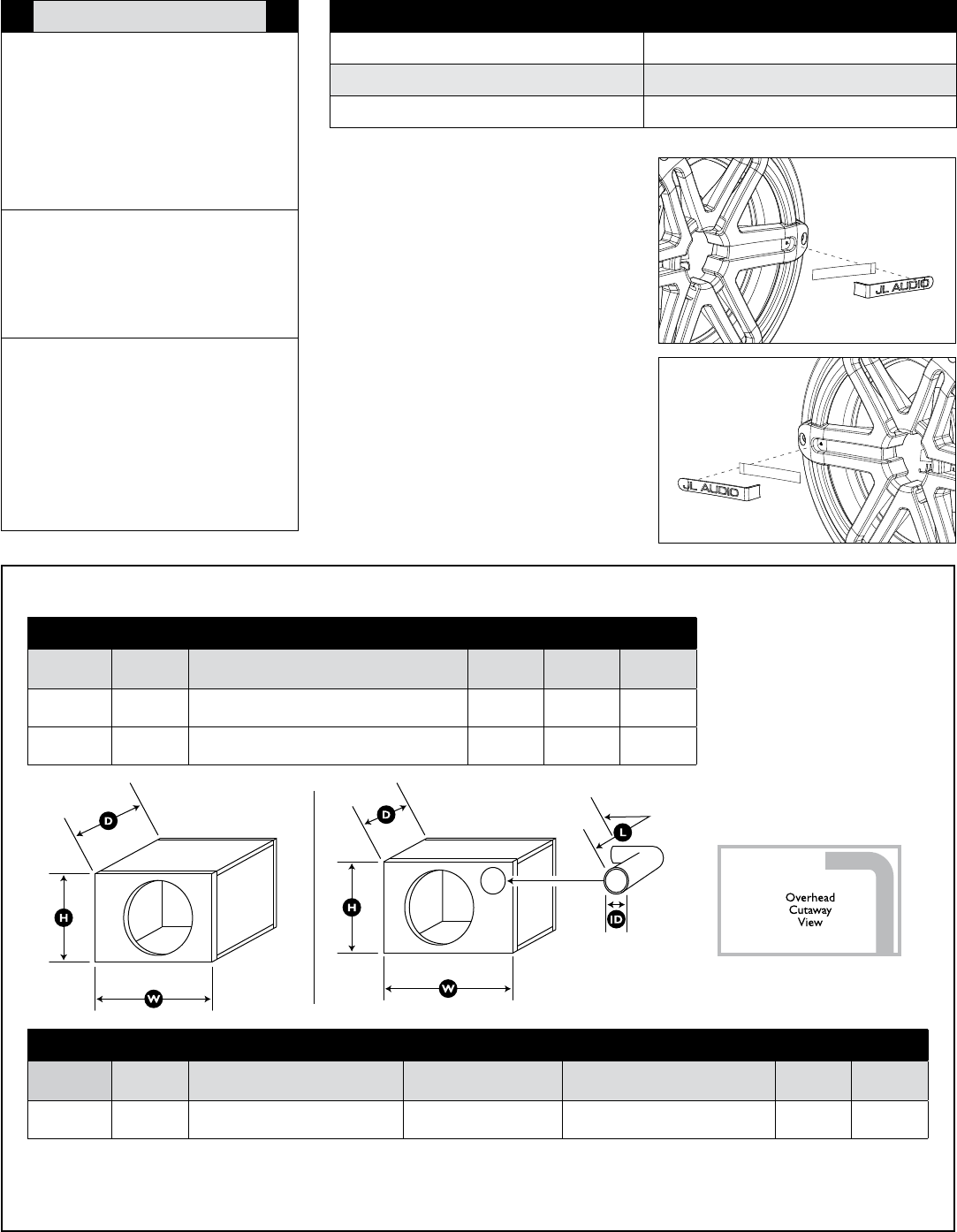
Subwoofer Recommended Sealed Design
Volume
(net int.)
External Dimensions
(Width x Height x Depth)
F3
(Hz)
Fc
(Hz)
Qtc
M10W5
0.875 ft³
24.8 litres
14 in. x 14 in. x 12 in.
356 mm x 356 mm x 305 mm
49 52.85 .770
M10IB5
2.50 ft³
70.8 litres
18 in. x 18 in. x 17.75 in.
457 mm x 457 mm x 451 mm
42 51.06 .918
Subwoofer Recommended Ported Design
Volume
(net int.)
Enclosure External Dimensions
(Width x Height x Depth)
Round Port Specs
(Inner Diameter x Length)
Port Information
Tune to:
(Hz)
F3
(Hz)
M10W5
1.250 ft³
35.4 litres
16.5 in. x 13.5 in. x 14 in.
419 mm x 343 mm x 356 mm
3 in. x 13 in.
76 mm x 330 mm
Round port requires a 90˚ elbow
to fit in the specified enclosure
32 34
Sealed Design Ported Design
ENCLOSURE SPECIFICATIONS
NOTE: The M10IB5 Marine Subwoofer is not
recommended for use in Ported Enclosures.