


2 JL AUDIO M10IB5/M10W5
A
C
B
E
D
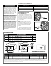
INSTALLATION PROCEDURE
The diagram above shows the typical
installation procedure into a fiberglass panel using
the supplied hardware (Classic Grille Model shown.
Installation is the same for Sport Grille Models).
Always follow proper safety procedures when
working on a vessel. Use eye-protection at all times
and a dust mask and gloves when cutting.
1) Choose a flat mounting surface that has
sufficient
depth and air space behind it to accept
the subwoofer.
2) Cut a 8.875-inch (225 mm) diameter hole.
3) Run the speaker cable to the mounting location.
4) Place the woofer in the hole and mark the screw
hole locations using a sharp, pointed tool.
5) Remove the woofer and drill a pilot hole
(see chart on next page) in each of the screw
locations. It is also advisable to use a hand-driven
countersink tool on each hole to further inhibit
gel-coat cracking of fiberglass panels.
6) Connect the speaker wires and place the woofer,
with its grille in place, into the opening (for Sport
Grille models, pay attention to where the logo
badge will added.
7) While holding the speaker firmly in its mounting
location, evenly snug the mounting screws in a
criss-cross pattern, then hand tighten in a criss-
cross pattern.
Non-standard installations may require different
hardware. Always use marine-grade, stainless-steel
fasteners to ensure a secure, reliable installation.
We recommend the use of this speaker in a bi-amplified system using high-quality satellite speakers and amplifiers.
We do not recommend the use of this subwoofer with a passive crossover (coil), as this type of device will adversely
affect performance.
All specifications are subject to change without notice.
PHYSICAL SPECIFICATIONS
INCLUDED PARTS
• One Polymer Subwoofer Grille
• Six #10 x 1 5/8-inch (41 mm) pan-head
stainless-steel screws
• Six #10 stainless-steel washers
• Logo Badges (Sport-Grille Models Only)
One Pair Black (White & Titanium/Black Models)
One Pair Red (White & Titanium/Black Models)
One Pair White (White Models Only)
One Pair Titanium (Titanium/Black Models Only)
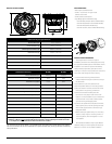
Subwoofer Physical Specifications
Nominal Diameter: 10 in. / 250 mm
Overall Diameter (A): 10.75 in. / 273 mm
Mounting Hole Diameter (B): 8.875 in. / 225 mm
Bolt Hole Circle (C): 9.706 in. / 247 mm
Motor Overmold Outer Diameter (D): 6.11 in. / 155 mm
Mounting Depth (E): 5.93 in. / 151 mm
Net Weight: 11.4 lbs. / 5.17 Kg
Driver Displacement: 0.064 ft / 1.81 litres
Subwoofer Parameters M10IB5 M10W5
Free Air Resonance (Fs): 42.20 Hz 31.55 Hz
Electrical “Q” (Qes): 0.819 0.484
Mechanical “Q” (Qms): 10.355 8.946
Total Speaker “Q” (Qts): 0.759 0.460
Equivalent Compliance (Vas): 1.16 ft3 / 32.85 litres 1.58 ft3 / 44.75 litres
One-way, Linear Excursion (Xmax)*: 0.52 in. / 13.2 mm 0.52 in. / 13.2 mm
Efficiency (1W/1m)**: 86.8 dB SPL 86.7 dB SPL
Effective Piston Area (Sd): 50.11 in² / 0.0323 m² 50.11 in² / 0.0323 m²
DC Resistance (Re): 4.167 ohm 3.602 ohm
Nominal Impedance: 4 ohm 4 ohm
Infinite Baffle Use: Yes No
Enclosure Use: Yes (Sealed Only) Yes (Sealed and Ported)
Power Handling (continuous): 250W 250W
* Xmax specifications are derived via one-way voice coil overhang method with no correction factors applied.
** Efficiency (1W/1m) is not an accurate indicator of a subwoofer’s output capability and should not be used
as a comparison to other subwoofers to determine which one is “louder” !