


IRIS MODEL P522 APPLICATION MANUAL
Page 24
Signal sources other than flame, such as incandes-
cent or fluorescent light, can cause false readings
that should be understood.
For example: fluorescent light is
nonsinusoidal in character, meaning that
there is a sharp peak when the fluores-
cent tube fires on the positive AC power
cycle with a less amplitude excursion on
the negative cycle, resulting in a radical
voltage swing in the amplifiers employed
in the viewing head. This sharp peak
causes the first-stage amplifiers (AGC
circuit for photovoltaic photodetectors)
to react violently, resulting in down-
stream signal perturbations that are not
normal. This can be even worse if a
strobe light is used as a signal source.
An incandescent light source is sinusoidal in char-
acter, resulting in a less “disturbing” signal for the
viewing head, but still does not resemble a true flame
source because of the large AC/DC component
present. The element in an incandescent light pro-
duces radiation in step with the AC power cycle, ef-
fectively turning on and off 120 times per second.
There is a certain amount of thermal inertia, so that
the element doesn’t turn off completely, but the large
ratio of ON to OFF (AC/DC) still prevails. A more
realistic, simulated signal source can be created by
employing an AC to DC power supply with super-
imposed ripple feeding an incandescent lamp. If the
120 Hz AC ripple is about 10 per cent, then this sig-
nal source can be used to more closely resemble a
flame source – keeping in mind that the simulated
flicker is a single frequency of 120 Hz.
Consideration should be given to the effects of pre-
senting a single-frequency, simulated flame source
to the downstream, four-position filter.
For example: if an incandescent light
source is used, powered by the 60 Hz line,
switching from LL to L position will not
affect the 120 Hz signal at all, because of
the cutoff frequency of 36 Hz and 71 Hz
respectively, providing the downstream
stages of amplification are not saturated
(sinusoidal 120 Hz signal amplified to re-
semble a squarewave caused by waveform
clipping of the operational amplifiers). If
this signal is saturated, then switching
from LL to L may indeed cause a higher
reading in the signal processor, caused by
the squarewave type waveform presented
to the filter. For this reason, it is impor-
tant not to judge the filter performance
when using this type of signal source.
In general, it is appropriate to use signal sources pow-
ered by the 60 Hz line for viewing head cursory check-
ing, but obviously not for definitive performance. No
detrimental effects will result from using signals that
saturate the viewing head amplifiers.
VIEWING HEAD - ANGLE OF VIEW
The angle of view of the IRIS S509 viewing head has
been specified at 2.8 degrees. A description of what
this means is given in this manual (see 2
nd
paragraph,
section DETERMINING SIGHT PIPE SIZE).
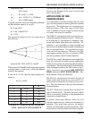
The angle of view is a function of the focal length of
the lens and the size of the photodetector element.
The equation for angle of view of a camera lens is:
2F tan θ/2 = d
where F = effective focal length of lens
θ = angle of view
d = diagonal of negative
so that the angle θ is:
θ = 2 tan
-1
d/2F
The diagonal of the negative is used for photographic
reasons related to the size of the negative, but a bet-
ter measure for the purposes of this explanation
would be the diameter of a circle. The photodetec-
tor element used for the S509 is 2.0 x 2.5 mm, which
is nearly square, and the longer side is used for the
angle-of-view calculation (2.8 degrees).
The PbS element used in the S512 is 2.0 x 2.0 mm
square. If you take the area of this element (4 mm
2
)
and find a circle of the same area, the diameter will
be 2.2568 mm. This was derived as follows: