


IRIS MODEL P522 APPLICATION MANUAL
Page 12
lecting the set points. For instance, selecting a flame
out set point that is equal to or greater than the flame
on set point will result in this error indication.
As well, the set points can be selected remotely through
the serial communication port using a host computer –
explained in greater detail later in this manual.
FLAME FAILURE RESPONSE
TIME (F.F.R.T.)
The flame failure response time, or F.F.R.T., is de-
fined as the time it takes for the flame relay to de-
energize after the flame signal (from the viewing
head) drops out. This time delay is programmable
from both the front panel of the P522 and a remote,
host computer. Only three settings are possible: one,
two and three seconds.
The maximum time delay is limited to three seconds
in compliance with the FM (Factory Mutual) limit
of the F.F.R.T. to not more than four seconds.
The P522 decision-making process occurs on a pe-
riodic basis, and the decision to start a F.F.R.T. time
delay before de-energizing the flame relay is initi-
ated every second in step with the sampling rate of
the flame signal. This means that the actual flame
out condition (i.e., drop-out of the flame signal from
the viewing head) will, in all probability, occur dur-
ing the sampling period that causes the actual
F.F.R.T. to be greater than the set time.
For example: suppose the signal from
the viewing head drops out immedi-
ately after a sampling from the P522,
and the sampling perceives flame to
be present. If the F.F.R.T. set point is
set for three seconds, there will be an
actual time delay of nearly four sec-
onds. In other words, the actual
F.F.R.T. will be the current set-point
time, plus an additional amount of
time not exceeding one second, de-
pending upon when the flame signal
from the viewing head drops out.
4-20mA REMOTE OUTPUT
The standard remote meter output has a 0-20mA
range and is designed to drive remote meters, as ex-
plained earlier in this manual. You can convert this
output to a 4-20mA range, as follows:
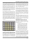
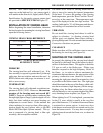
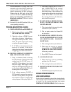
Press the front panel push-buttons (indicated
in the table below) while holding down both
the ⇑ and ⇓ buttons. Press all in each row
together (i.e., three in the first row, two in
the second row, and three in the last row).
Doing this toggles the function back and forth be-
tween the 0-20mA and 4-20mA ranges.
The change will be verified by four dashes “----”
and “4-20” momentarily displayed. If the module is
programmed for the 4-20mA range, “4-20” will be
displayed; toggling back to the 0-20mA range will
again cause four dashes to appear on power-up of
the unit. Tha factory default setting are 4-20.
One thing to consider when feeding the 4-20mA sig-
nal to a remote computer or DCS, is that there is no
isolation between the P522 ground and the remote
system ground. If there is a ground potential differ-
ence between the two systems, then there could be
serious noise and performance problems. You will
not encounter this problem when using a remote
meter by itself, because it will not be tied into an-
other electrical system (will not be sharing grounds).
The bargraph reading on the front panel will not be
affected by this change to 4-20mA output. It will re-
main the same as before (i.e., go to zero on no signal
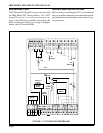
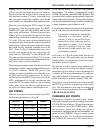
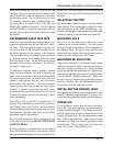
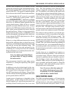
FIGURE 6 - REMOTE METER ANALOG
OUTPUT
EMALF
NO
EMALF
FFO
TESNIAGTRFF
LEDEMIT
NO
XXX
XX
XXX