


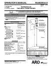
WLM2203A-XXPage4of4
PLACING INTO SERVICE
AIR AND LUBRICATION REQUIREMENTS
Filteredair willhelpextendthe lifeofthepump, allowingthepumpto op-
erate more efficiently and yield longer service life to moving parts and
mechanisms.
• Installanairlinefiltertoprovidegoodqualitycleananddryair.Install
it up stream from the regulator.
• Use an airregulator ontheair supplyto control thepump cyclerate.
Install the regulator as close as possible to the pump.
• Inmostinstallations,lubricationisnotrequired.Ifthepump needsto
havelubrication,installanairlinelubricatorandsupplyitwithagood
grade of non-detergent oil or other lubricant compatible with Nitrile
seals and set at a rate not to exceed one drop per minute.
INSTALLATION
• Mount and secure the pump as required for the application.
• Attach a ground wire from the pump ground screw to a suitable
ground.
• Connectafluidhosetothepumpoutlet.Inmostcasesapipesealant
should be used on thread connection. Tighten all fittings. Use cau-
tion not to damage threads.
OPERATION
START-UP
1. Turn the air regulator to “0” pressure setting.
2. Immerse the lower pump end into the material.
3. Open the dispensing device.
4. Startthepump cyclingslowly byraisingthe pressureto 1.4- 2.1bar
(20 - 30 p.s.i.).
5. Close the dispensing device. Allow the pump to stall and build line
pressure.Check foranyleaks andtightenfittingsas needed.Adjust
pressure as required for the application.
SHUTDOWN
• Disconnecttheairsupplyfromthepumpifitistobeinactiveforafew
hours. Open the dispensing device to relieve line pressure.
SERVICE
PUMP DISASSEMBLY / REASSEMBLY
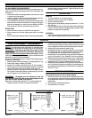
NOTICE: The unique design of this pump allows for quick basic pump
service without total removal from the drum (refer to the views below).
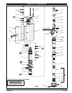
DISASSEMBLY
- Allthreadsarerighthand.Refertofigure2.These
proceduresarefortheinstallationofrepairkitparts.Disconnectair
supply andrelieve all systempressure
prior to servicing. Carefully
removetheparts,inspectpartsfordamage,nicksorexcessivewearand
determine if any parts will need replacement.
Follow the three disassembly steps in the detail views below and place
the pump on a clean bench.
1. Remove (1)bolts.Remove(18)packing, (17)bushingand(16) “O”ring.
2. Remove (36) adapter, releasing (10) muffler.
3. Grasp the (11) cylinder and remove the (20, 14) piston assembly.
4. Remove(15)lowercap and(3)trackgasket. Remove(12)retaining
ring and (48) washer, then pull (14) piston off (20) piston rod.
5. Remove(2) cap and (3) track gasket. Push onthe large o.d. end of
the(7)spooltoremovethe(4)sleeve.Grabthenoseof(7)spooland
pull out. Repeat for other sleeve and spool.
REASSEMBLY
- Thoroughly clean and lubricate all seals and
bores with Shell Gadus S2U1000 upon assembly. Replace allsoft
parts with new ones included in the repair kit.
Note: Refer to the illustration (figure 2) for “U” cup lip seal direction.
1. Replace the seals on both the (7) spools and (4) sleeves.
2. Locate the valve chamber on the (11) cylinder where the 3/8’’ dia.
hole is locatedand installone of the(4) sleeves.Insert the(7) spool
from the opposite end. Next, install the remaining sleeve and spool.
3. Replace the (3) track gasket and install (2) cap.
4. Replacethe(13)piston “U”cups(refertofigure 2forproper orienta-
tion).Replace the (19)“O”ringand assemble(14) pistonto(20)pis-
ton rod and retain with (48) washer and (12) retaining ring.
5. Installthe (20, 14) pistonassembly using great care tocollapse the
outer lip of the second “U” cup, allowing it to slip into the cylinder.
6. Replacethe (3) track gasket andinstall the(15) cap. Installthe (16)
“O” ring ontothe piston rod, replace(17) bushing and (18)packing.
7. Replace the (25) “O” ring and re-attach the (24) inner check.
8. Slidethe pump assembly back into the (26)base / lowerpump sec-
tion.Pressthesectionstogetherandaligntheairinletandpumpout-
letasrequiredand replacethefour(1)boltsand(27) nuts(tighten to
9 Nm (79.7 in. lbs).
TROUBLE SHOOTING
If the pump will not cycle or will not deliver material.
• Becertaintocheckfornon-pumpproblemsincludingkinked,restric-
tiveorpluggedinlet/outlethoseordispensingdevice.Depressurize
the pump system and clean out any obstructionsin the inlet / outlet
material lines.
• Check all seals, including track gaskets.
• Check direction of “U” cup lips.
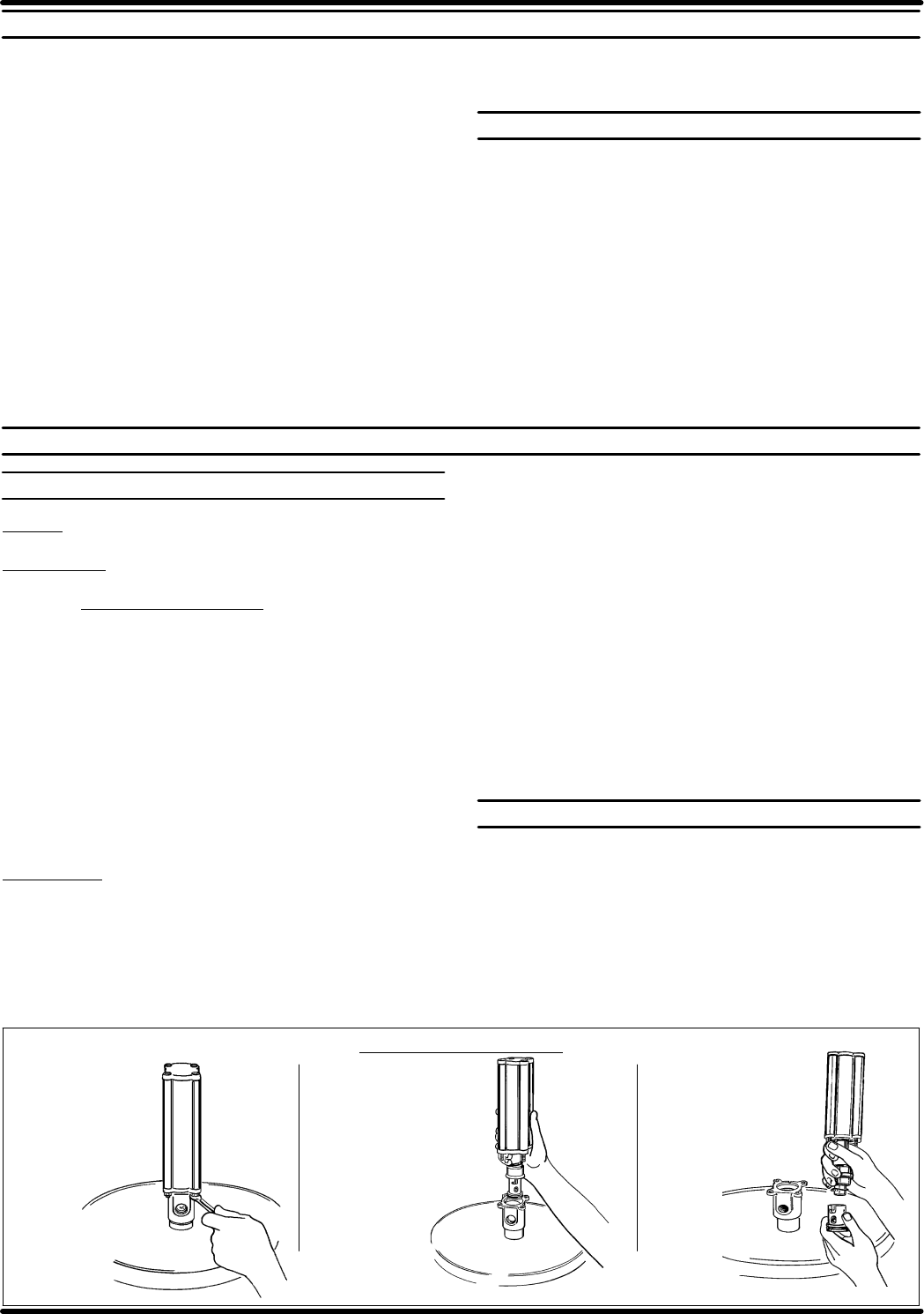
C) Unlock the (24) inner
check from the pistonrod.
Figure 5
Figure 4
B) Grasp the lower motor cap
and pull out the motor and
upper section of the lower
section.
PUMP DISASSEMBLY DETAIL
Figure 3
A) Remove the four
nuts from the base
of the Air Motor.
PN 97999-865