


WLM2203A-XXPage2of4
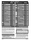
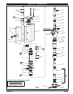
PARTS LIST / WLM2203A-XX
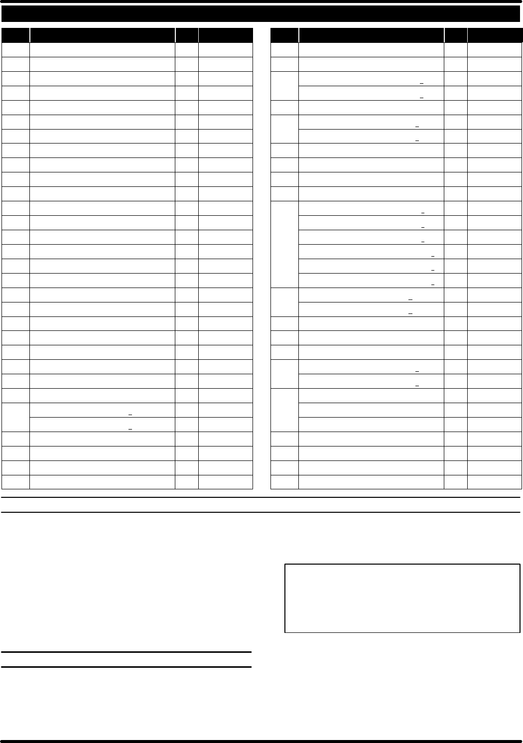
Item Description (size in inches) Qty Part No. Item Description (sizein inches) Qty Part No.
1 Bolt (4) 94333
2 Upper Cap (1) 95035
n 3 Track Gasket (2) 94311
4 Sleeve (2) 94316
n 5 “O” Ring (1/16”x 11/16” o.d.) (4) Y325-15
n 6 “O” Ring (1/8”x 3/4” o.d.) (4) Y325-206
7 Spool (2) 94310
n 8 “U” Cup (1/8” x 3/4”o.d.) (2) Y240-7
n 9 “O” Ring (.106”x .587” o.d.) (2) 15066-PM
10 Muffler (1) 95037
11 Cylinder (1) 94249
12 Retaining Ring (1) 94406
n 13 “U” Cup (3/16” x 2” o.d.) (2) Y240-23
14 Piston (1) 94780
15 Lower Cap (1) 95038
n 16 “O” Ring (1/8” x 1-3/8” o.d.) (1) Y325-216
17 Bushing (1) 94332
n 18 Packing (1/4” x 1-5/8” o.d.) (1) 94337
n 19 “O” Ring (3/32” x 1” o.d.) (1) Y325-117
20 Piston Rod (1) 94779
21 Groove Pin (3/16” o.d. x1 -1/8” long) (1) 94338
22 Spring (1) 94705
23 Ball (.7500” dia.) (1) Y16-224
24 Inner Check (1) 94279
n 25 “O” Ring (3/16”x 1-7/16” o.d.) (1) Y325-319
26 Base (models WLM2203A-X1) (1) 94309
(models WLM2203A-X2) (1) 94309-1
27 Nut (4) 93828
n 28 Copper Gasket (1) 96031
29 Tube (1) 94314-1
n 30 “O” Ring (3/32”x 1-9/16” o.d.) (1) Y325-126
31 Ball (1.000” dia.) (1) 90532-6
32 Ball Stop Pin (.187” dia. x 1.430” long) (1) 94339
33 Foot Valve (models WLM2203A-X1) (1) 94315
(models WLM2203A-X2) (1) 94315-1
n 34 “O” Ring (1/16”x 7/16” o.d.) (1) Y325-11
36 Adapter (models WLM2203A-X1) (1) 94447
(models WLM2203A-X2) (1) 94447-1
37 Foam Liner (2) 95039
38 Ground Screw (#10 - 32x 1/4”) (1) 93005
39 Bung Ass’y (includes items 40and 49) (1) 67145-3-B
40 Thumb Screw (1/4” -20 x 1-1/2”) (1) Y197-158-C
41 Pipe Extension -(models WLM2203A-31) (1) 94523-3
3/4 - 14N.P.T. x30- 1/8” - (modelsWLM2203A-41) (1) 94523-4
3/4 - 14N.P.T. x37- 3/4” - (modelsWLM2203A-51) (1) 94523-5
Rp 3/4 (3/4 - 14 BSPtaper x20- 3/8”) - (WLM2203A-32) (1) 94537-3
Rp 3/4 (3/4 - 14 BSPtaper x30- 1/8”) - (WLM2203A-42) (1) 94537-4
Rp 3/4 (3/4 - 14 BSPtaper x37- 3/4”) - (WLM2203A-52) (1) 94537-5
42 Valve Housing (WLM2203A -X1) (1) 94535
(WLM2203A-X2) (1) 94535-1
43 Ball Guide (1) 77904
44 Ball (1.0000” dia.) (1) Y16-232
n 45 “O” Ring (3/32”x 1-7/16” o.d.) (1) Y325-124
46 Ball Seat (models WLM2203A-X1) (1) 94534
(models WLM2203A-X2) (1) 94534-1
47 Valve Ass’y (includes items42 thru 46)
(models WLM2203A-31, -41, -51) (1) 67085
(models WLM2203A-32, -42, -52) (1) 67085-1
48 Washer (1) 94515
49 Nut (1/4” - 20) (1) Y12-4-C
n Gadus S2 U1000 Grease Packet (1) 94833
n Parts in Repair Kit 637224
GENERAL DESCRIPTION
Model WLM2203A-XX series two-ball double acting pumps are in-
tendedtobeusedprimarilyforoiltransferanddeliverysystems.Itisbest
to usethis pumpwith low -- medium viscosityfluids. Ituses carbonsteel
and other materials which make it compatible with most petroleum
based lubricationproducts. Thetwo-ball designprovides betterpriming
ofthelowerfoot valve.Doubleacting pumpswilldeliver materialonboth
the up and down stroke.
NOTE: If this pump was purchased separately (not part of a system),
consult your sales representative for compatible dispensing accesso-
ries which will best match the application. All accessories must be able
to withstand the maximum pressure developed by the pump.
OPERATING AND SAFETY PRECAUTIONS
READ THE GENERAL INFORMATION MANUAL INCLUDED FOR
ADDITIONAL OPERATING AND SAFETY PRECAUTIONS AND
OTHER IMPORTANT INFORMATION.
STAT IC SPARK. Can cause explosion resulting in severe injury or
death. Ground the pump and pumping system.
EXCESSIVE INLET PRESSURE. Can cause explosion resulting in
severe injury or death. Do not exceed maximum operating
pressure of 25.5 bar (370 p.s.i.) at 8.5 bar (123 p.s.i.) inlet air
pressure.Donotrunpumpwithoutusingaregulatortolimitair
supply pressure to the pump.
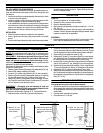
PUMP RATIO X
INLET PRESSURE TO PUMP MOTOR
=
MAXIMUM PUMP
FLUID PRESSURE
Pumpratioisanexpressionoftherelationshipbetweenthepumpmotorareaand
the lowerpump end area. EXAMPLE:When 125 p.s.i. (8.6 bar) inlet pressure is
supplied to the motor of a3:1 ratio pump itwill develop a maximum of 375p.s.i.
(25.9bar) fluid pressure (at noflow) -- as thefluidcontrolis opened,theflow rate
will increase as themotor cycle rate increases to keep up with the demand.
EXCESSIVE MATERIAL PRESSURE. C an cause equipment f ailure
resultinginsevereinjury orpropertydamage.Donot exceedthe
maximum material pressure of any component in the system.
NOTICE:Thermalexpansioncan occurwhenthefluidinthemateri-
al lines is exposed to elevated temperatures. Example: Material
lines locatedin a non-insulated roofarea can warmdue to sunlight.
Install a pressure relief valve in the pumping system.
Replacement warning label (pn 94520) is available upon request.