


Page 3 of 8PM10X-XXX-XXX-A02 (en)
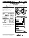
GENERAL DESCRIPTION
The ARO diaphragm pump offers high volume delivery even at low air
pressure and a broad range of material compatibility options available.
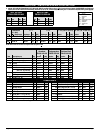
Refer to the model and option chart. ARO pumps feature stall resistant
design, modular air motor / fluid sections.
Air operated double diaphragm pumps utilize a pressure differential in
the air chambersto alternately createsuctionand positive fluidpressure
in the fluid chambers, ball checks insure a positive flow of fluid.
Pump cycling will begin as air pressure is applied and it will continue to
pump and keep up with the demand. It will build and maintain line pres-
sure and will stop cycling once maximum line pressure is reached (dis-
pensing device closed) and will resume pumping as needed.
AIR AND LUBE REQUIREMENTS
WARNING
EXCESSIVE AIR PRESSURE. Can cause pump
damage, personal injury or property damage.
S A filter capableoffiltering outparticles largerthan50 micronsshould
be used ontheair supply. There isnolubrication required other than
the “O” ring lubricant which is applied during assembly or repair.
S If lubricatedairispresent,makesurethatitis compatiblewiththe“O”
rings and seals in the air motor section of the pump.
INSTALLATION
S
Verify correct model / configuration prior to installation.
S Retorque all external fasteners per specifications prior to start up.
S Pumps aretestedin water atassembly. Flush pumpwithcompatible
fluid prior to installation.
S When the diaphragm pump is used in a forced-feed (flooded inlet)
situation, it is recommended that a “Check Valve” be installed at the
air inlet.
S Material supply tubing should be at least the same diameter as the
pump inlet manifold connection.
S Material supply hose must be reinforced, non-collapsible type com-
patible with the material being pumped.
S Piping must be adequately supported. Do not use the pump to sup-
port the piping.
S Use flexible connections (such as hose) at the suction and dis-
charge. These connections should not be rigid piped and must be
compatible with the material being pumped.
S Secure the diaphragm pump legs to a suitable surface (level and
flat) to insure against damage by vibration.
S Pumps that need to besubmersedmusthave both wet and non-wet
components compatible with the material being pumped.
S Submersed pumps must have exhaust pipe above liquid level. Ex-
haust hose must be conductive and grounded.
S Flooded suction inlet pressure must not exceed 10 p.s.i.g. (0.69
bar).
OPERATING INSTRUCTIONS
S
Always flush the pump with a solvent compatible with the material
being pumped if the materialbeing pumped is subject to “settingup”
when not in use for a period of time.
S Disconnect theair supply fromthe pump ifit is tobe inactive forafew
hours.
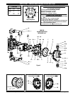
PARTS AND SERVICE KITS
Refer tothe part viewsand descriptions asprovided on page4 through 7
for parts identification and Service Kit information.
S Certain ARO “Smart Parts” are indicated which should be available
for fast repair and reduction of down time.
S Service kits are divided to service two separate diaphragm pump
functions:1.AIRSECTION,2.FLUIDSECTION.TheFLUIDSEC-
TION is divided further to match typical part MATERIAL OPTIONS.
MAINTENANCE
S
Provide a clean work surface to protect sensitive internal moving
parts from contamination from dirtandforeign matter during service
disassembly and reassembly.
S Keep good records of service activity and include pump in preven-
tive maintenance program.
S Before disassembling, empty captured material in the outlet man-
ifold by turning the pump upside down to drain material from the
pump.
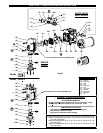
FLUID SECTION DISASSEMBLY
1. Remove (61) outlet manifold, (60) inlet manifold.
2. Remove (22) balls, (19 and 33) “O” rings (if applicable) and (21)
seats.
3. Remove (15) fluid caps.
NOTE: Only PTFE diaphragm models use a primary diaphragm (7) and
a backup diaphragm (8). Refer to the auxiliary view in the Fluid Section
illustration.
4. Remove the (14) screw, (6) diaphragm washer, (7) or (7 / 8) dia-
phragms, and (5) backup washer.
NOTE: Do not scratch or mar the surface of (1) diaphragm rod.
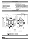
FLUID SECTION REASSEMBLY
S
Reassemble in reverse order. Refer to the torque requirements on
page 5.
S Clean and inspect all parts. Replace worn or damaged parts with
new parts as required.
S Lubricate (1) diaphragm rod and (144) “U” cup with LubriplateR
FML-2 grease (94276 grease packet is included in service kit).
S For modelswithPTFE diaphragms: Item(8) Santoprene diaphragm
is installed with the side marked “AIR SIDE” towards the pump cen-
ter body. Install the PTFE diaphragm (7) with the side marked
“FLUID SIDE” towards the (15) fluid cap.
S Re-check torque settings after pump has been re-started and run a
while.
S LoctiteR and242R are registered trademarks ofHenkel Loctite Corporation S AROR is aregistered trademark of Ingersoll-Rand Company S
S SantopreneR is aregistered trademark of Monsanto Company, licensed toAdvanced Elastomer Systems, L.P., SLubriplateR is aregistered trademark of Lubriplate Division (Fiske Brothers Refining Company) S
S 271t is a trademark of Henkel Loctite Corporation S