


PH15F-XXX-XXX-X (en) Page 5 of 8
15
181
70
1
68
26
144
175
43
78
27
131
180
21
21
19
22
61
26
78
60
63
60
5
69
195
19
70
144
126�
77
77
76
15a
76
9
14
29
26
6
8
19
19
(models PH15F-AXX-XXX
and PH15F-BXX-XXX)
(model PH15F-FXX-XXX)
2
61
(model PH15F-FXX-XXX)
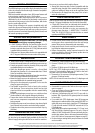
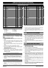
ASSEMBLY TORQUE REQUIREMENTS
NOTE: DO NOT OVERTIGHTEN FASTENERS.
ALL FASTENERS ARE METRIC.
(14) Cap Screws 50-55 Ft-Lbs (67.8 - 74.6 Nm).
(26) Manifold Screws 20 - 25 Ft-Lbs (27.1- 33.9 Nm).
(27) Fluid Cap 15-20 Ft-Lbs (20.3 - 27.1 Nm).
(131) Screws 12-17 Ft-Lbs (16.3 - 23 Nm).
LUBRICATION / SEALANTS
Apply Lubriplate FML-2 grease to all “O” rings, “U” cups and mating parts.
Apply Loctite® 262™ to threads at assembly.
Apply PTFE tape to threads at assembly.
Apply Loctite 271™ to threads.
Apply anti-seize compound to threads and bolt and nut flange heads
which contact pump case when using stainless steel fasteners.
Apply 96998 3/8” wide x 1/8” thick Joint Sealant (aproximately 27.12”
long) to air cap (item 68 only) diaphragm bead groove. Use ONLY 1
wrap of sealant. DO NOT overlap seam. Fill seam with heavy duty an-
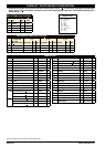
aerobic pipe sealant. Seam to be located between bolt positions 1 and
3 (refer to “Torque Sequence” diagram).
Lubriplate FML-2 is a white food grade petroleum grease.
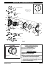
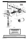
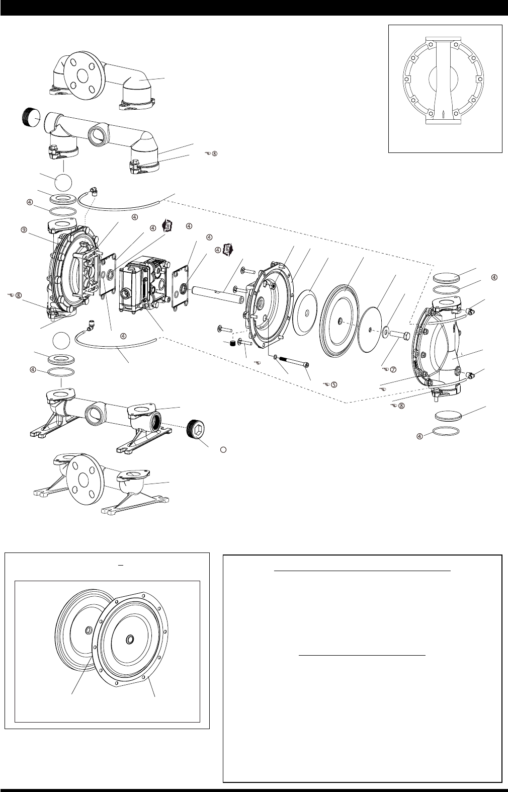
PARTS LIST / PH15F-XXX-XXX-X FLUID SECTION
View for PH15F-XXX-XXT-X (PTFE diaphragm)
conguration only.
(Santoprene)
8
(PTFE)
7
FOR THE AIR MO-
TOR SECTION, SEE
PAGES 6 & 7.
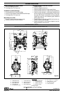
Torque Sequence
Figure 2
3
2
7
5
1
8
10
6
4
9