


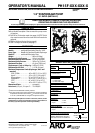

PH15F-XXX-XXX-X (en) Page 3 of 8
Hytrel® and Viton® are registered trademarks of the DuPont Company
Loctite® and 242® are registered trademarks of Henkel Loctite Corporation
Santoprene® is a registered trademark of Monsanto Company, licensed to Advanced Elastomer Systems, L.P.
ARO® is a registered trademark of Ingersoll-Rand Company
Lubriplate® is a registered trademark of Lubriplate Division (Fiske Brothers Rening Company)
271™ is a trademark of Henkel Loctite Corporation
Be sure not to use hose which might collapse..
Always ush the pump with a solvent compatible with the
material being pumped if the material being pumped is
subject to “setting up” when not in use for a period of time.
Disconnect the air supply from the pump if it is to be in-
active for a few hours.
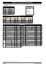
PARTS AND SERVICE KITS
Refer to the part views and descriptions as provided on page 4
through 7 for parts identication and Service Kit information.
Certain ARO “Smart Parts” are indicated which should be
available for fast repair and reduction of down time.
Service kits are divided to service two separate dia-
phragm pump functions: 1. AIRSECTION, 2. FLUIDSEC-
TION. The FLUID SECTION is divided further to match
typical part MATERIAL OPTIONS.
MAINTENANCE
Provide a clean work surface to protect sensitive internal
moving parts from contamination from dirt and foreign
matter during service disassembly and reassembly.
Keep good records of service activity and include pump
in preventive maintenance program.
Before disassembling, empty captured material in the
outlet manifold by turning the pump upside down to
drain material from the pump.
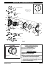
FLUID SECTION DISASSEMBLY
Remove (61) outlet manifold and (60) inlet manifold.
Remove (22) balls, (19) “O” rings, (21) seats and (76) seat
plugs.
Remove (15) uid cap and (15a) uid cap.
NOTE: Only PTFE diaphragm models use a primary dia-
phragm (7) and a backup diaphragm (8). Refer to the auxil-
iary view in the Fluid Section illustration.
4. Remove the (14) cap screw, (6) diaphragm washer, (7) dia
-
phragm, (5) backup washer.
NOTE: Do not scratch or mar the surface of (1) diaphragm rod.
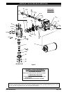
FLUID SECTION REASSEMBLY
Reassemble in reverse order. Refer to the torque require-
ments on page 5.
Clean and inspect all parts. Replace worn or damaged
parts with new parts as required.
Lubricate (1) diaphragm rod and (144) “U” cups with Lu-
briplate® FML-2 grease (94276 grease packet is included
in service kit).
For models with PTFE diaphragms: Item (8) Santoprene
diaphragm is installed with the side marked “AIR SIDE” to-
wards the pump center body. Install the PTFE diaphragm
(7) with the side marked “FLUID SIDE” towards the (15) or
(15a) uid caps.
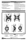
Apply 96998 joint sealant (approximately 27.12” long) to air
cap (item 68 only) diaphragm groove. Use only 1 wrap of
sealant. DO NOT overlap seam. Fill seam with heavy duty an-
aerobic pipe sealant. Seam to be located between bolt posi-
tion 1 and 3 (refer to “torque sequence” diagram on page 5)”.
Re-check torque settings after pump has been re-started
and run a while.
1.
2.
3.
GENERAL DESCRIPTION
The ARO diaphragm pump oers high volume delivery even
at low air pressure and a broad range of material compatibil-
ity options available.
Refer to the model and option chart. ARO pumps feature stall
resistant design, modular air motor / uid sections.
Air operated double diaphragm pumps utilize a pressure
dierential in the air chambers to alternately create suction
and positive uid pressure in the uid chambers, ball checks
insure a positive ow of uid.
Pump cycling will begin as air pressure is applied and it will
continue to pump and keep up with the demand. It will build
and maintain line pressure and will stop cycling once maxi-
mum line pressure is reached (dispensing device closed) and
will resume pumping as needed.
AIR AND LUBE REQUIREMENTS
WARNING
EXCESSIVE AIR PRESSURE. Can cause pump
damage, personal injury or property damage.
A filter capable of filtering out particles larger than 50
microns should be used on the air supply. There is no lu-
brication required other than the “O” ring lubricant which
is applied during assembly or repair.
If lubricated air is present, make sure that it is compatible with
the “O” rings and seals in the air motor section of the pump.
INSTALLATION
Verify correct model / conguration prior to installation.
Retorque all external fasteners per specications prior to start up.
Pumps are tested in water at assembly. Flush pump with
compatible uid prior to installation.
When the diaphragm pump is used in a forced-feed
(ooded inlet) situation, it is recommended that a “Check
Valve” be installed at the air inlet.
Material supply tubing should be at least the same diam-
eter as the pump inlet manifold connection.
Material supply hose must be reinforced, non-collapsible
type compatible with the material being pumped.
Piping must be adequately supported. Do not use the
pump to support the piping.
Use flexible connections (such as hose) at the suction
and discharge. These connections should not be rigid
piped and must be compatible with the material being
pumped.
Secure the diaphragm pump legs to a suitable surface
(level and at) to insure against damage by vibration.
Pumps that need to be submersed must have both wet
and non-wet components compatible with the material
being pumped.
Submersed pumps must have exhaust pipe above liquid
level. Exhaust hose must be conductive and grounded.
Flooded suction inlet pressure must not exceed 10 p.s.i.g.
(0.69 bar).
OPERATING INSTRUCTIONS
The outlet material volume is governed not only by the air sup-
ply, but also by the material supply available at the inlet. The
material supply tubing should not be too small or restrictive.