


Page 6 of 12 PD05X-XXX-XXX-B (en)
n
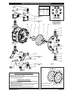
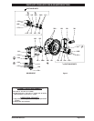
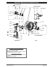
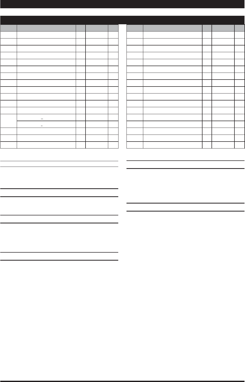
Indicates parts included in uid section service kit, see page 4.
MATERIAL CODE
[A] = Aluminum [D] = Acetal
[B] = Nitrile [SS] = Stainless Steel
[C] = Carbon Steel [U] = Polyurethane
[Ck] = Ceramic [Z] = Zinc
AIR MOTOR SECTION SERVICE
Service is divided into two parts - 1. Pilot Valve, 2. Major Valve.
Air Motor Section service is continued from Fluid Section repair.
PILOT VALVE DISASSEMBLY
Remove (123) screws, releasing (103) covers, (121) washers,
(118) actuator pins and (167) pilot piston.
Remove (170) spool bushing and inspect inner bore of bushing
for damage.
PILOT VALVE REASSEMBLY
Clean and lubricate parts not being replaced from service kit.
Assemble (171) “O” rings to (170) bushing and assemble bush-
ing into (101) center body.
Lubricate and assemble (167) pilot piston assembly into (170)
bushing.
Assemble (173 and 174) “O” rings and (121) washers to (103)
covers, then insert (118) actuator pins through assembly.
Assemble (144) “U” cups (note the lip direction) and (103) cov-
ers to (101) center body, securing with (123) screws. NOTE:
tighten (123) screws to 10 - 12 in. lbs (1.13 - 1.36 Nm).
y
1.
2.
1.
2.
3.
4.
5
.
MAJOR VALVE DISASSEMBLY
Unthread (134) bolts, releasing (129) exhaust cover.
Pull (135) valve block and components from (101) center body.
Remove (132) gasket, (141) valve plate and (140) valve insert
from (135) valve block.
Remove (134) bolts, releasing (136) plug and (111) spool.
MAJOR VALVE REASSEMBLY
Assemble new (139 and 138) “U” cups on (111) spool - LIPS
MUST FACE EACH OTHER.
Assemble (137) “O” rings to (136) large plug.
Insert (111) spool into (136) large plug, then insert (136) large
plug into (135) valve block, being sure the (111) spool is rotated
to accept (140) valve insert.
Assemble (140) valve insert and (141) valve plate to (135) valve
block. NOTE: Assemble (140) valve insert with “dished” side
toward (141) valve plate. Assemble (141) valve plate with iden-
ti cation dot toward (132) gasket.
Assemble (132 and 200) gaskets, (135) valve block, (130) gasket
and (129) exhaust cover to (101) center body, securing with
(134) bolts. NOTE: Tighten (134) bolts to 15 - 20 in. lbs (1.7 - 2.3
Nm).
1.
2.
3.
4.
1.
2.
3.
4.
5
.
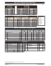
PARTS LIST / PX05A-XXX-XXX-B AIR MOTOR SECTION
AIR MOTOR PARTS LIST
Item Description
(size)
Qty Part No. Mtl
101 Center Body (1) 95978 [A]
103R Cover
(right side)
(1) 96091 [D]
103L Cover
(left side)
(1) 96351 [D]
111 Major Valve Spool (1) 95919 [D]
118 Actuator Pin (2) 97111 [SS]
p
121 Washer (2) 96092 [D]
123 Screw
(#4 - 20 x 1/2”)
(8) 96093 [SS]
129 Exhaust Cover (1) 95979 [A]
130 Gasket (1) 96632 [B]
p
132 Air Manifold Gasket (1) 96214-1 [B]
134 Flange Bolt
(1/4” - 20 x 5-3/4”)
(4) 94871 [SS]
135 Valve Block (1) 95980 [Z]
136
Plug, Large
(PD05A-XXX-XXX-B)
(1) 95982 [A]
(PE05A-XXX-XXX-B)
(1) 96464 [A]
p
137 “O” Ring
(1/16” x 1-5/8” o.d.)
(2) Y325-29 [B]
p
138 “U” Cup Packing
(1/8” x 1” o.d.)
(1) 94395 [U]
p
139 “U” Cup Packing
(1/8” x 1-7/16” o.d.)
(1) 96383 [U]
Item Description
(size)
Qty Part No. Mtl
140 Valve Insert (1) 93276 (Ck)
141 Valve Plate (1) 96173 (Ck)
np
144 “U” Cup Packing
(3/16” x 1” o.d.)
(2) Y187-48 [B]
p
167 Pilot Piston
(includes 168 and 169)
(1) 67382 [D]
168 "O” Ring
(1/16” x 7/16” o.d.)
(2) 96459 [U]
169 “U” Cup Packing
(1/8” x 5/8” o.d.)
(1) 96384 [U]
170 Spool Bushing (1) 96090 [D]
p
171 “O” Ring
(1/16” x 13/16” o.d.)
(2) Y325-17 [B]
p
173 “O” Ring
(3/32” x 7/8” o.d.)
(2) Y325-115 [B]
np
174 “O” Ring
(3/32” x 11/32” o.d.)
(2) Y325-105 [B]
p
200 Porting Gasket (1) 96364 [B]
201 Mu er (1) 93110 [C]
p
232 “O” Ring
(1/16” x 3/8” o.d.)
(4) Y325-10 [B]
250 Screw
(1/4” - 14 x 1/2” o.d.)
(1) Y334-104-C [C]
n
p
Lubriplate FML-2 grease (1) 94276
Lubriplate Grease Packets (10) 637308
p
Indicates parts included in 637428 air section service kit.