


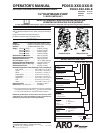

PD05X-XXX-XXX-B (en) Page 3 of 12
y
Hytrel® and Viton® are registered trademarks of the DuPont Company
y
Kynar® is a registered trademark of Arkema Inc.
y
ARO® is a registered trademark of Ingersoll-Rand Company
y
y
Santoprene® is a registered trademark of Monsanto Company, licensed to Advanced Elastomer Systems, L.P.
y
Loctite® and 242® are registered trademarks of Henkel Loctite Corporation
y
y
572™ is a trademark of Henkel Loctite Corporation
y
Lubriplate® is a registered trademark of Lubriplate Division (Fiske Brothers Re ning Company)
y
MAINTENANCE
Certain ARO “Smart Parts” are indicated which should be avail-
able for fast repair and reduction of down time.
Provide a clean work surface to protect sensitive internal mov-
ing parts from contamination from dirt and foreign matter dur-
ing service disassembly and reassembly.
Keep good records of service activity and include the pump in
preventive maintenance program.
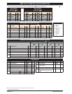
Service kits are available to service two separate diaphragm
pump functions: 1. AIR SECTION, 2. FLUID SECTION. The Fluid
Section is divided further to match typical part Material Op-
tions.
Before disassembling, emptycaptured material in the outlet
manifold by turning the pump upside down to drain material
from the pump.
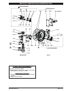
DIAPHRAGM PUMP SERVICE
GENERAL SERVICE NOTES:
Inspect and replace old parts with new parts as necessary. Look
for deep scratches on metallic surfaces, and nicks or cuts in “O”
rings.
Tools needed to complete disassembly and repair:
7/8” wrench, 1/2” socket or wrench, 3/8” socket or wrench,
3/8” Allen wrench, 10 mm Allen wrench, T-10 Torx screw-
driver, torque wrench (measuring inch pounds), “O” ring
pick.
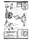
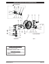
FLUID SECTION DISASSEMBLY
Remove (61) top manifold.
Remove (19) “O” rings, (21) seats, (12) washers (where appli-
cable) and (22) balls.
Remove (60) bottom manifold.
Remove (19) “O” rings, (21) seats, (12) washers (where appli-
cable) and (22) balls.
Remove (15) uid caps.
Remove (14) bolt, (6) diaphragm washer, (7) or (7 / 8) dia-
phragms and (5) washer.
Remove (1) connecting rod from air motor.
Carefully remove remaining (14) bolt, (6) diaphragm washer, (7)
or (7 / 8) diaphragms and (5) washer from (1) connecting rod.
Do not mar surface of connecting rod.
FLUID SECTION REASSEMBLY
Reassemble in reverse order.
Lubricate (1) connecting rod with Lubriplate® or equivalent “O”
ring lubricant.
Connecting rod (1) should be installed using 96571 bullet, in-
cluded in service kit.
Install (5) washers with i.d. chamfer toward diaphragm.
When replacing PTFE diaphragms, install the 93465 Santo-
prene diaphragm behind the PTFE diaphragm.
y
y
y
y
y
y
y
y
1.
2.
3.
4.
5.
6.
7.
8.
y
y
y
y
y
GENERAL DESCRIPTION
The ARO diaphragm pump o ers high volume delivery even at low
air pressure and a broad range of material compatibility options are
available. Refer to the model and option chart. ARO pumps feature
stall resistant design, modular air motor / uid sections.
Air operated double diaphragm pumps utilize a pressure di eren-
tial in the air chambers to alternately create suction and a positive
fluid pressure in the fluid chambers, ball checks insure a positive
ow of uid.
Pump cycling will begin as air pressure is applied and will continue
to pump and keep up with the demand. It will build and maintain
line pressure and will stop cycling once maximum line pressure is
reached (dispensing device closed) and will resume pumping as
needed.
AIR AND LUBE REQUIREMENTS
WARNING
EXCESSIVE AIR PRESSURE. Can cause pump dam-
age, personal injury or property damage.
A lter capable of ltering out particles larger than 50 microns
should be used on the air supply. There is no lubrication re-
quired other than the “O” ring lubricant which is applied during
assembly or repair.
If lubricated air is present, make sure that it is compatible with
the “O” rings and seals in the air motor section of the pump.
OPERATING INSTRUCTIONS
Always ush the pump with a solvent compatible with the ma-
terial being pumped if the material being pumped is subject to
“setting up” when not in use for a period of time.
Disconnect the air supply from the pump if it is to be inactive
for a few hours.
The outlet material volume is governed not only by the air sup-
ply, but also by the material supply available at the inlet. The
material supply tubing should not be too small or restrictive.
Be sure not to use hose which might collapse.
When the diaphragm pump is used in a forced-feed ( ooded
inlet) situation, it is recommended that a “check valve” be in-
stalled at the air inlet.
Secure the diaphragm pump legs to a suitable surface to insure
against damage by vibration.
y
y
y
y
y
y
y