


PE03P-X-X-A0S (en)Page 6 of 12
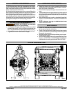
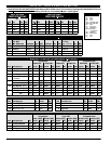
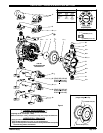
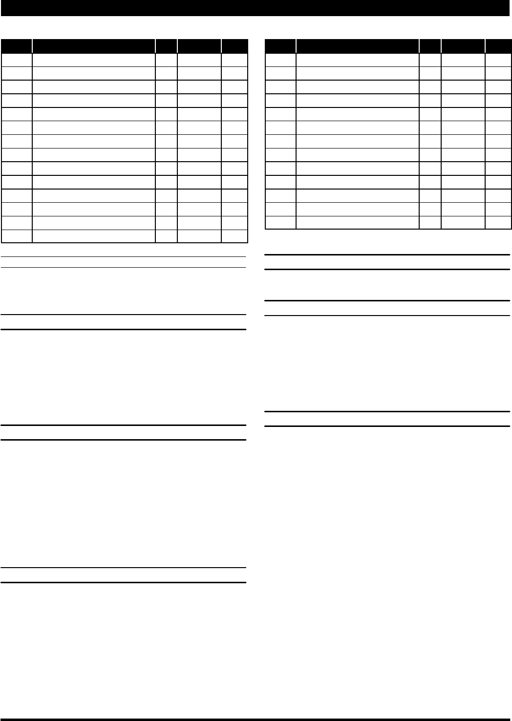
PARTS LIST / PE03P-X-X-A0S AIR MOTOR SECTION
(n) Indicates parts included in 637428 Air Section Repair Kit.
Item Description (size) Qty Part No. [Mtl] Item Description (size) Qty Part No. [Mtl]
101 Center Body (1) 96570 [PPG]
103R Cover (right side) (1) 96488 [D]
103L Cover (left side) (1) 96489 [D]
118 Actuator Pin (2) 94874-1 [SS]
121 Washer (2) 96092 [D]
123 Screw (#4-20x1/2”) (12) 96093 [SS]
128 Plug (#10 -32 x 5/32”) (2) 59632-1 [Ny]
129 Muffler Baffle (1) 96542 [P]
130 Gasket (1) 96531 [SY]
n 132 Air Manifold Gasket (1) 96214-1 [B]
133 Washer (9/32” i.d. x 5/8” o.d.) (4) 93096 [SS]
134 Flange Bolt (1/4” -20 x 1-1/2”) (4) Y6-47-T [SS]
135 Porting Plate (1) 96382 [PPG]
n 144 “U” Cup Packing (1/8” x 3/4” o.d.) (2) Y187-47 [B]
n 167 Pilot Piston (includes 168 and 169) (1) 67382 [D]
168 “O” Ring (1/16” x 7/16” o.d.) (2) 96459 [U]
169 “U” Cup Packing (1/8” x 5/8” o.d.) (1) 96384 [U]
170 Spool Bushing (1) 96090 [D]
n 171 “O” Ring (1/16” x 13/16” o.d.) (2) Y325-17 [B]
n 173 “O” Ring (3/32” x 7/8” o.d.) (2) Y325-115 [B]
n 174 “O” Ring (3/32” x 1 1/32” o.d.) (2) Y325-105 [B]
n 200 Porting Gasket (1) 96364 [B]
n 232 “O” Ring (1/16” x 3/8” o.d.) (4) Y325-10 [B]
236 Nut (1/4” - 20) (4) Y12-4-S [SS]
n Lubriplate FML-2 Grease (1) 94276
Lubriplate Grease, 10 Pack 637308
MATERIAL CODE
[B] = Nitrile [PPG] = Glass Filled Polypropylene
[D] = Acetal [SS] = Stainless Steel
[Ny] = Nylon [SY] = Syn-Seal
[P] = Polypropylene [U] = Polyurethane
DIAPHRAGM PUMP SERVICE
GENERAL SERVICE NOTES:
S Inspect and replace old parts with new parts as necessary. Look for
deep scratches on metallic surfaces, and nicks or cuts in “O” rings.
S Tools needed to complete disassembly and repair:
S 5/8” socket or wrench, 7/16” socket or wrench, 3/8” socket or
wrench, 5/16” Allen wrench, T-10 Torx screwdriver, torque
wrench (measuring inch pounds), “O” ring pick.
FLUID SECTION DISASSEMBLY
1. Remove (61) top manifold.
2. Remove (19) “O” rings, (21) seats and (22) balls.
3. Remove (60) bottom manifold.
4. Remove (19) “O” rings, (21) seats and (22) balls.
5. Remove (15) fluid caps.
6. Remove (6)diaphragm nut,(7) or(7 /8) diaphragms and(5) washer.
7. Remove (1) connecting rod from air motor.
8. Carefully remove remaining (6) diaphragm nut, (7) or (7 / 8) dia-
phragms and (5) washer from (1) connecting rod. Do not mar sur-
face of connecting rod.
FLUID SECTION REASSEMBLY
S Reassemble in reverse order.
S Lubricate (1) connecting rod with Lubriplate or equivalent “O” ring
lubricant.
S Install (5) washers with i.d. chamfer toward diaphragm.
S When replacing PTFE diaphragms, install the 96533-A Santoprene
diaphragm behind the PTFE diaphragm.
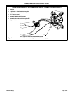
AIR MOTOR SECTION SERVICE
S Air Motor Section Service is continued from Fluid Section repair.
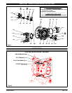
PILOT VALVE DISASSEMBLY
1. Remove (123)screws, releasing (103)covers, (121) washers,(118)
actuator pins and (167) pilot piston.
2. Remove (170) spool bushing and inspect inner bore of bushing for
damage.
3. Unthread (123) screws, releasing (129) muffler baffle.
4. Unthread (134) bolts and pull (135) porting plate and (132 and 200)
gaskets from (101) center body.
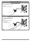
PILOT VALVE REASSEMBLY
1. Clean and lubricate parts not being replaced from service kit.
2. Assemble (171) “O” rings to (170) bushing and assemble bushing
into (101) center body.
3. Lubricate andassemble (167) pilotpiston assemblyinto (170)bush-
ing.
4. Assemble (173 and 174) “O” rings and (121) washers to (103) cov-
ers, then insert (118) actuator pins through assembly.
5. Assemble (144) “U” cups (note the lip direction) and (103) covers to
(101) centerbody, securingwith(123) screws.NOTE:Tighten (123)
screws to 4 - 6 in. lbs (0.45 - 0.68 Nm).
6. Assemble (132 and 200) gaskets and (135) porting plate to center
body, securing with (134)bolts.NOTE: Tighten (134)boltsto 15 - 20
in. lbs (1.7 - 2.3 Nm).
7. Assemble (130)gasket and(129) muffler baffle to(101) centerbody,
securing with (123) screws. NOTE: Tighten (123) screws to 4 - 6 in.
lbs (0.45 - 0.68 Nm).