


PD30X-X-BPage 6 of 8
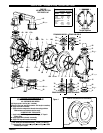
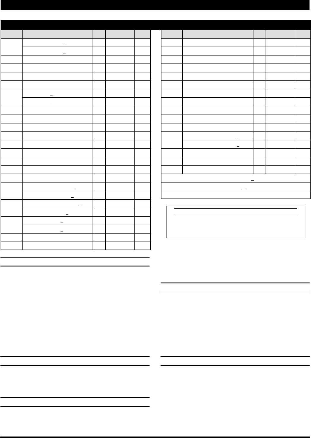
PARTS LIST / PD30X-X-X-B( ) AIR SECTION
n Indicates parts included in 637302 Air Section Service Kit shown below and items (70), (144), (175) and (180) shown on page 4.
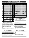
AIR MOTOR PARTS
Item Description (size) Qty Part No. [Mtl] Item Description (size) Qty Part No. [Mtl]
101 Center Body (PD30A-X-X-B) (1) 94028 [A]
(PD30S-X-X-B) (1) 94109 [SS]
103 Bushing (1) 94092 [D]
107 Inlet Plug (1) 94034 [C]
109 Piston (1) 92011 [D]
n 110 “U” Cup (1-3/8” o.d.) (1) Y186-51 [B]
111 Spool (PD30A-X-X-B) (1) 92005 [A]
(PD30S-X-X-B) (1) 93047 [C]
112 Washer (1.556” o.d.) (5) 92877 [Z]
n 113 “O” Ring (small) (1/8” x 1-1/4” o.d.) (5) Y325-214 [B]
n 114 “O” Ring (large) (3/32” x 1-9/16” o.d.) (7) Y325-126 [B]
V 115 Spacer (4) 92876 [Z]
116 Spacer (1) 94027 [A]
118 Actuator Pin (0.250” x 2.276”) (2) 94083 [SS]
121 Sleeve (2) 94084 [D]
~ 127 90_ St. Elbow (1-1/2 -11-1/2 N.P.T.) (1) 94860 [C / I ]
n 132 Gasket (valve body) (1) 94099 [B]
133 Lockwasher (1/4”) (PD30A-X-X-B) (3) Y117-416-C [C]
(PD30S-X-X-B) (3) Y14-416-T [SS]
134 Screw (M6x1.0x16mm)(PD30A-X-B) (4) 96721030 [C]
(PD30S-X-X-B) (4) 96720081 [SS]
135 Valve Block (PD30A-X-X-B) (1) 94032 [A]
(PD30S-X-X-B) (1) 94318 [SS]
136 Piston Plug (1) 94033 [D]
n 146 “O” Ring z (3/32” x 1-1/16” o.d.) (1) Y325-118 [B]
n 147 “O” Ring z (1/8” x 1/2” o.d.) (2) Y325-202 [B]
n 166 Track Gasket D (1) 94026 [B]
n 167 Pilot Piston (includes 168 and 169) (1) 67164 [D]
168 “O” Ring (3/32” x 5/8” o.d.) (2) 94433 [U]
169 “U” Cup (1/8” x 7/8” o.d.) (1) Y240-9 [B]
170 Piston Sleeve (1) 94081 [Br]
n 171 “O” Ring (3/32” x 1-1/8” o.d.) (1) Y325-119 [B]
n 172 “O” Ring (1/16” x 1-1/8” o.d.) (1) Y325-22 [B]
n 173 “O” Ring (1/16” x 1-3/8” o.d.) (2) Y325-26 [B]
Ln174 “O” Ring (1/8” x 1/2” o.d.) (2) Y325-202 [B]
n 176 Diaphragm (check valve) (2) 94102 [SP]
n 177 Retaining Ring (PD30X-XXP-X-B) (1) Y147-16-C [C]
n (PD30X-XXS-X-B) (1) Y147-16-S [SS]
~ 201 Muffler (1) 94810
Ln Lubriplate FML-2 Grease (1) 94276
Lubriplate Grease Packets (10) 637308
z Used on Stainless Steel models (PD30S-XXX-XXX-B) only.
D Used on Aluminum models (PD30A-XXX-XXX-B) only.
~ Items not shown.
MATERIAL CODE
[A] = Aluminum [D] = Acetal [SS] = Stainless Steel
[B] = Nitrile [I] = Iron [U] = Polyurethane
[Br] = Brass [SP] = Stantoprene [Z] = Zinc
[C] = Carbon Steel
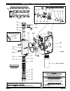
AIR MOTOR SECTION SERVICE
Service is divided into two parts - 1. Pilot Valve, 2. Major Valve.
GENERAL REASSEMBLY NOTES:
S Air Motor Section Service is continued from Fluid Section repair.
S Inspect and replace old parts with new parts as necessary. Look for
deep scratches on metallic surfaces, and nicks or cuts in “O” rings.
S Take precautions to prevent cutting “O” rings upon installation.
S Lubricate “O” rings with Lubriplate FML-2 grease.
S Do not over-tighten fasteners, refer to torque specification block on
view.
S Re-torque fasteners following restart.
S SERVICE TOOLS -- To aid in the installation of (168) “O” rings onto
the (167) pilot piston, use tool # 204130-T, available from ARO.
PILOT VALVE DISASSEMBLY
1. A light tap on (118) should expose the opposite (121) sleeve, (167)
pilot piston and other parts.
2. Remove (170) sleeve and inspect inner bore of sleeve for damage.
PILOT VALVE REASSEMBLY
1. Clean and lubricate parts not being replaced from service kit.
2. Install new (171 and 172) “O” rings, replace (170) sleeve.
3. Install new(168)“O” rings and(169) seal -- Note thelip direction.Lu-
bricate and replace (167).
4. Reassemble remaining parts, replace (173 and 174) “O” rings.
MAJOR VALVE DISASSEMBLY
1. Remove (135) valve block, exposing gaskets (166 and 132) and
(176) checks.
2. Remove (177) snap ring and (107) inlet plug.
3. On thesideopposite the airinlet,push on the innerdiameter of (111)
spool. Thiswillforce the (136)piston plug and (109)piston out. Con-
tinue pushing the (111) spool and remove. Check for scratches or
gouges.
4. Remove the Major Valve parts (112 - 116).
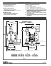
MAJOR VALVE REASSEMBLY
1. Replace (112) washer, (114) “O” ring and (113) “O” ring onto (115)
spacer and insert etc. Continue this routine to build the major valve
stack.
NOTE: Becareful to orientspacer legs awayfrom blocking internal
ports.
2. Replace (111) spool on (136) plug, (110) seal on (109) piston and
replace (109), (136) plug and (177) snap ring.
V “Smart Parts”, keep these items on hand in addition to the service kits for fast repair and reduction of down time.