


PD03P-XXX-XXX (en) Page 7 of 12
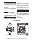
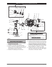
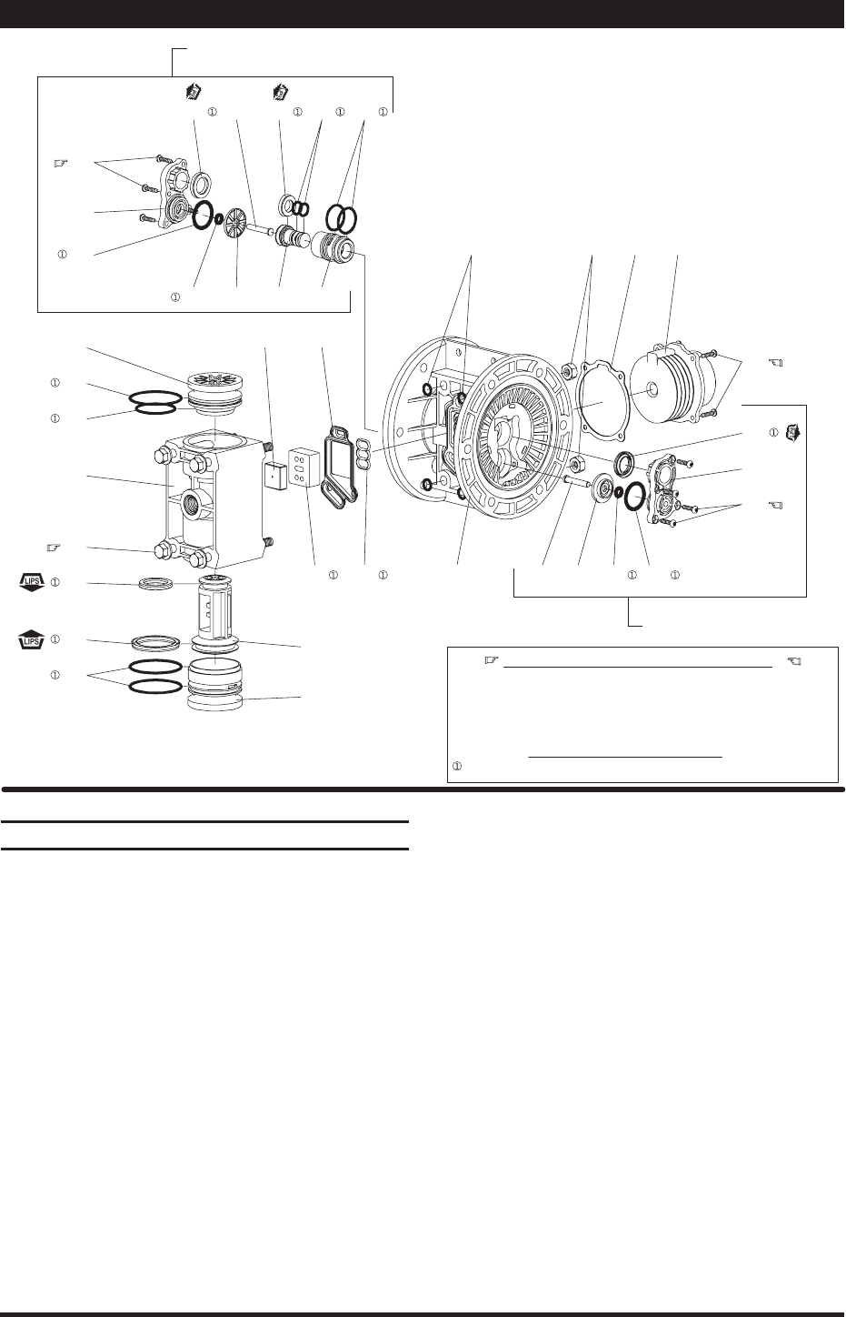
PILOT VALVE PARTS
Figure 4
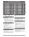
ASSEMBLY TORQUE REQUIREMENTS
NOTE: DO NOT OVERTIGHTEN FASTENERS.
(123) screw, 4 - 6 in. lbs (0.45 - 0.68 Nm).
Apply Lubriplate (94276) to all “O" rings, ”U" cups and mating parts.
(134) bolt, 15 - 20 in. lbs (1.7 - 2.3 Nm), wait 10 minutes, then re-torque to 15
- 20 in. lbs (1.7 - 2.3 Nm).
LUBRICATION / SEALANTS
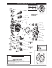
135
137
136
111
174
132
134
166
138
139
137
144
103R
123
173 121118
107
141 200 101
140
129130
123
103L
144 169 168 171 118
167121 174 170
173
MAJOR VALVE
PILOT VALVE PARTS
232 236
123
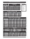
PARTS LIST / PD03P-XXX-XXX AIR MOTOR SECTION
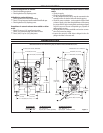
MAJOR VALVE REASSEMBLY
Assemble new (139 and 138) U” cups on (111) spool -
LIPS MUST FACE EACH OTHER.
Assemble (137) O” rings to (136) large plug.
Assemble (137 and 166) O” rings to (107) small plug.
Insert (111) spool into (136) large plug, then insert (136)
large plug into (135) valve block, being sure the (111)
spool is rotated to accept (140) valve insert.
Assemble (107) small plug into (135) valve block.
1.
2.
3.
4.
5.
Assemble (140) valve insert and (141) valve plate to
(135) valve block. Note: Assemble (140) valve insert with
dished” side toward (141) valve plate. Assemble (141)
valve plate with identi cation dot toward (132) gasket.
Assemble (132 and 200) gaskets and (135) valve block
to (101) center body, securing with (134) bolts. NOTE:
Tighten (134) bolts to 15 - 20 in. lbs (1.7 - 2.3 Nm).
Assemble (130) gasket and (129) mu er ba e to (101)
center body, securing with (123) screws. NOTE: Tighten
(123) screws to 4 - 6 in. lbs (0.45 - 0.68 Nm).
6.
7.
8.