


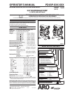


PD03P-XXX-XXX (en) Page 3 of 12
GENERAL DESCRIPTION
The ARO diaphragm pump offers high volume delivery even
at low air pressure and a broad range of material compatibility
options available. Refer to the model and option chart. ARO
pumps feature stall resistant design, modular air motor / uid
sections.
Air operated double diaphragm pumps utilize a pressure dif-
ferential in the air chambers to alternately create suction and
positive uid pressure in the uid chambers, ball checks insure
a positive ow of uid.
Pump cycling will begin as air pressure is applied and it will
continue to pump and keep up with the demand. It will build
and maintain line pressure and will stop cycling once maxi-
mum line pressure is reached (dispensing device closed) and
will resume pumping as needed.
AIR AND LUBE REQUIREMENTS
WARNING
EXCESSIVE AIR PRESSURE. Can cause pump
damage, personal injury or property damage.
A filter capable of filtering out particles larger than 50
microns should be used on the air supply.
There is no lu-
brication required other than the “O” ring lubricant which is
applied during assembly or repair.
If lubricated air is present, make sure that it is compatible
with the “O” rings and seals in the air motor section of
the pump.
y
y
Viton
®
and Hytrel
®
are registered trademarks of the DuPont
®
Company Loctite
®
is a registered trademark of Henkel Loctite Corporation
Santoprene
®
is a registered trademark of Monsanto Company, licensed to Advanced Elastomer Systems, L.P. Lubriplate
®
is a registered trademark of Lubriplate Division (Fiske Brothers Re ning Company)
OPERATING INSTRUCTIONS
Always flush the pump with a solvent compatible with
y
MAINTENANCE
Certain ARO “Smart Parts” are indicated which should be
available for fast repair and reduction of down time.
Provide a clean work surface to protect sensitive internal
moving parts from contamination from dirt and foreign
matter during service disassembly and reassembly.
Keep good records of service activity and include pump
in preventive maintenance program.
Service Kits are available to service two separate Dia-
phragm Pump functions: 1. AIR SECTION, 2. FLUID SEC-
TION. The Fluid Section is divided further to match typical
active MATERIAL OPTIONS.
y
y
y
y
the material being pumped if the material being pumped
is subject to “setting up” when not in use for a period of
time.
Disconnect the air supply from the pump if it is to be in-
active for a few hours.
The outlet material volume is governed not only by the
air supply but also by the material supply available at the
inlet. The material supply tubing should not be too small
or restrictive. Be sure not to use hose which might col-
lapse.
When the diaphragm pump is used in a forced-feed
( ooded inlet) situation, it is recommended that a Check
Valve” be installed at the air inlet.
Secure the diaphragm pump legs to a suitable surface to
insure against damage by vibration.
y
y
y
y
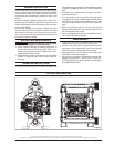
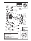
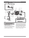
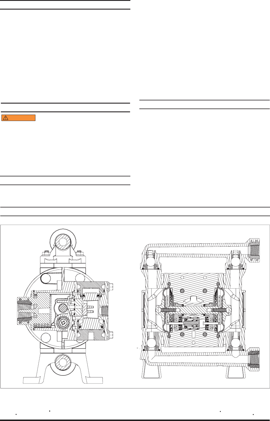
TYPICAL CROSS SECTION
Figure 2