


PAGE4OF4 6696X-X
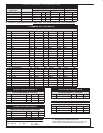
PACKING
OPTIONS AND SER
VICE KITS
LOWER PUMP SERVICE KIT UPPER PACKING LOWER PKG
51 (X) ``V"PACKING 52 (3) ``V" PACKING 70 PACKING 65 (2) PACKING
6696X-XXX
63724X-XX3 PART NO QTY. MT'L PART NO MT'L PART NO MT'L PART NO MT'L
-1X3 J 637240-F43 93688-1 (6) [L] 92963-1 [L]
-8X3 J 637240-F43 93688-4 (3) [UH] 93688-1 [L] 92963-4 [UH]
-A33 J 637241-C33 93355-1 [UH] 92963-4 [UH]
-B33 J 637241-C33 93355-1 [UH] 92963-4 [UH]
-C13 J, C43 637240-C43 93688-4 (6) [UH] 92963-4 [UH]
-C33 J 637241-C33 93355-1 [UH] 92963-4 [UH]
J AS OF MAY 15, 1995 NO LONGER AVAILABLE
// EXAMPLE: 66960-113 is replaced by 66960-F43 & Service kit is 637240-F43
LOWER
PUMP DISASSEMBL
Y
1. Unscrew six (22) cap screws to remove (19) ball seat assembly, two
(20) ``O" rings and two (21) balls.
2. Unscrew three (4) screws and remove (6) cap, two (14) balls and
(15) ``O" ring.
3. Unscrew (1) adjustable packing nut and remove (115) female washer,
six (51) or (51)
(3)
/(52)
(3)
``V" packings, (53) male washer and (43) wave
spring. Unscrew (2) packing adapter and remove (38) gasket.
4. Unscrew four (12) nuts and remove (13) lockwashers (If req'd) and
(11) head and seat assembly.
5. Unscrew four (10) tie rods from (18) housing and (11) head and seat
assembly.
6. Pull two (17) tubes from (18) housing and remove two (16) ``O" rings
from each (11) tube.
7. Pull (9) tube from (18) housing and remove two (7) gaskets.
8. Pull (26) pump rod and piston cup assembly from (9) tube.
9. Unscrew (30) nut and remove piston cup assembly and (25) gasket
from (26) pump rod.
10. To disassemble piston cup assembly, unscrew two (36) nuts. This
will enable the two (66) washers and two (65) piston cups to be reĆ
moved from (29) follower.
LOWER
PUMP REASSEMBL
Y
• Clean and lubricate parts upon reassembly.
Use Loctite Anti-Seize on threads of 66961-XXX assemblies.
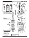
• Refer to parts view on page 3 for packing direction.
1. Place two (65) cups onto (29) follower as shown in figure 2 with two
(66) back up washers.
2. Retain two (65) cups in place using two (36) nuts. Torque nuts to
45-50 ft lbs.
3. Slip (25) gasket and piston cup assembly onto (26) pump rod.
4. Screw (30) nut onto (26) pump rod to retain piston cup assembly.
Torque to 45-50 ft lbs.
5. Thoroughly grease (9) tube. Place piston cup assembly into (9)
tube.
6. Place (18) housing in a vise and secure. Screw two (10) rods into
(18) housing.
7. Place four (16) ``O" rings onto two (17) tubes. Place two (17) tubes
into (18) housing. Place two (7) gaskets into (18) housing and (11)
head and seat assembly. Place (9) tube onto (18) housing.
8. Screw two (10) rods into (11) head and seat assembly.
9. Insert (38) gasket and screw (2) packing adapter into (11) cylinder
head. Insert (43) wave spring, (53) male washer, six (51) or
(51)
(3)
/(52)
(3)
``V" packings and (115) female packing washer into (11)
head and seat assembly. Screw (1) adjustable packing nut loosely
onto (11) head and seat assembly.
10. Position (11) head and seat assembly over (9) tube, (17) tubes and
two (10) rods. Screw two (12) nuts onto two (10) rods protruding
thru (11) head and seat assembly. Tighten after other two (12) nuts
are assembled. Torque (12) nuts to 25-30 ft lbs.
11. Place two (14) balls over two holes located in (11) head and seat
assembly.
12. Be sure (15) ``O" ring is positioned in groove at bottom of (6) cap
(replace if necessary). Place (6) cap in position over (11) head and
seat assembly. Screw three (4) screws into (6) cap. Torque screws
to 25-30 ft lbs.
13. Release assembly from vise and lay on work bench.
14. Tighten two (12) nuts protruding through (18) housing to secure
(18) housing to (9) tube. Torque (12) nuts to 25-30 ft lbs.
15. Position two (21) balls over two ports located in (18) housing. Be
sure two (20) ``O" rings are in place on (19) plate.
16. Place (19) plate over (18) housing and secure by using six (22)
screws. Torque screws to 25-30 ft-lbs. Tighten (2) adapter, torque
to 100-110 ft lbs.
PN 97999-051