


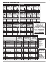
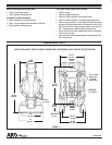
AIR
AND LUBE REQUIREMENTS
MAINTENANCE CONT’D
PAGE 3 OF 8
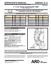
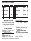
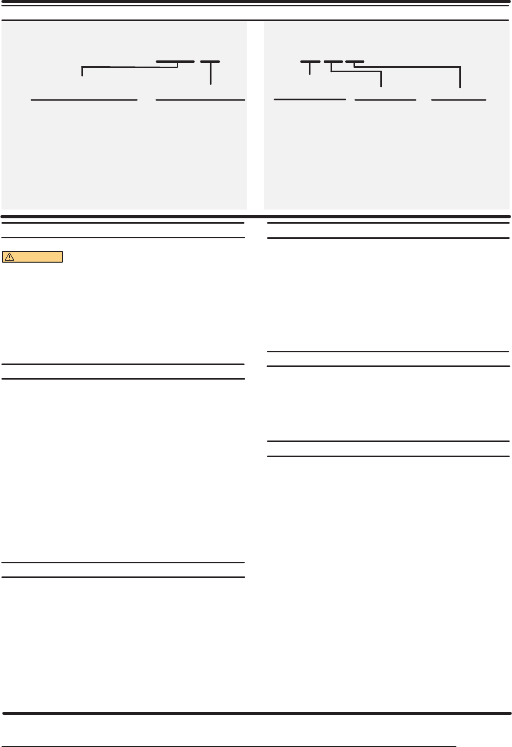
666DXX-X-C
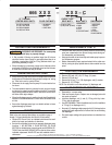
MODEL
DESCRIPTION CHART
WARNING EXCESSIVE AIR PRESSURE. Can cause pump
damage, personal injury or property damage.
S A filter capable of filtering out particles larger than 50 microns
should be used on the air supply. In most applications there is no
lubrication required other than the ``O"ring lubricant which is apĆ
plied during assembly or repair.
S When lubricated air is necessary, supply the air lubricator with a
good grade of SAE 90 wt. non-detergent oil and set the lubricator
to a rate not to exceed one drop per minute.
OPERATING INSTRUCTIONS
S Always flush the pump with a solvent compatible with the material
being pumped if the material being pumped is subject to "setting
up" when not in use for a period of time.
S Disconnect the air supply from the pump if it is to be inactive for a
few hours.
S The outlet material volume is governed not only by the air supply
but also by the material supply available at the inlet. The material
supply tubing should not be too small or restrictive. Be sure not to
use hose which might collapse.
S When the diaphragm pump is used in a forced-feed (flooded inlet)
situation it isrecommendedthata ``Check Valve" be installed at the
air inlet.
S Secure the diaphragm pump legs to a suitable surface to insure
against damage by vibration.
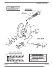
MAINTENANCE
Refer to the part views and descriptions as provided on page 4
through 7 for parts identification and Service Kit information.
S Certain ARO ``Smart Parts" are indicated which should be availĆ
able for fast repair and reduction of down time.
S Service kits are divided to service two separate diaphragm pump
functions: 1. AIR SECTION, 2. FLUID SECTION. The FLUID
SECTION is divided further to match typical part MATERIAL OPĆ
TIONS. Order the VALVE SERVICE KIT for repair of all fourvalves,
individual replacement VALVE KITS are also available which inĆ
clude seats.
S Provide a clean work surface to protect sensitive internal moving
parts from contamination from dirt and foreign matter during serĆ
vice disassembly and reassembly.
S Keep good records of service activity and include pump in prevenĆ
tive maintenance program.
S Before disassembling empty captured material in the outlet manĆ
ifold by turning the pump upside down to drain material from the
pump.
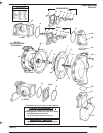
FLUID SECTION DISASSEMBL
Y
1. Remove top manifold(s).
2. Remove (22) balls, (19), (33) ``O" Rings, (21) seats.
3. Remove (15) fluid caps.
4. Remove the (6) nut, (7) or (7/8) diaphragms, and (5) washers.
5. Remove (3), (4) ``O"Rings.
NOTE: Do not scratch or mar the surface of (1) diaphragm rod.
FLUID SECTION REASSEMBL
Y
S Reassemble in reverse order.
S Clean and inspect all parts. Replace worn or damaged parts with
new parts as required.
S Lubricate diaphragm rod (1) and (2) ``O"ring with Key-LubeR
``O"ring lube or equivalent.
S Use ARO PN/98930-T Bullet (installation tool) to aid in installation
of ``O"ring (2) on diaphragm rod (1).
S Be certain (7) diaphragms align properly with (15) fluid caps before
making final torque adjustments on bolt and nuts to avoid twisting
the diaphragm.
S Re-check torque settings after pump has been re-started and run
a while.
666 X X X – X X X – C
FLUID CAP MAT’L
BALL MAT’L
DIAPHRAGM
1 NEOPRENE
2 BUNA
3 VITON
5 E.P.R.
8 POLYURETHANE
5 (FLAP) S'STEEL
7 (FLAP) PVDF (KYNAR)
0 ALUMINUM
1 S'STEEL
2 CAST IRON
CHECK TYPE
SEAT MAT’L
1 NEOPRENE
2 BUNA N
3 VITON R
5 E.P.R.
9 HYTRELR
B SANTOPRENER
(2’’ THREAD)
CENTER BODY MAT’L
(REV)
D0 NPT,ALUMINUM
D1 NPT, CAST IRON
D2 BSP, ALUMINUM
D3 BSP, CAST IRON
S VitonR andHytrelR aretrademarks ofthe DuPontCompany, S KynarR is atrademark of Penwalt Corp,
S SantopreneR isa registeredtrademark ofMonsanto Company,licensed toAdvanced Elastomer Systems,L.P. S Key-Lubeis atrademark ofKey Industries.