


Page 3 of 4
66650
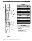
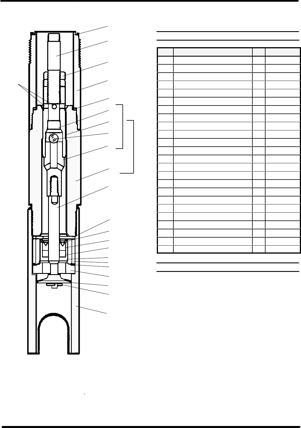
FIGURE 2
1
2
3
4
5
6
7
8
9
10
11
12
13
14
15
16
17
18
19
20
21
22
23
FLUID
PASSAGE
24
F032
LOWER PUMP
PARTS LIST
ITEM Description Qty Part No.
1 Gasket 1 70834
2 Rod 1 79240
3 Nut 2 Y11-106-C
4 Tube 1 79239
5 Gasket 1 70837
6 Ball Stop 1 83276
7 Plunger 1 71127
8 Ball 1 Y16-209
9 Adapter 1 70817
10 Suction Tube 1 71126
11 Primer Rod 1 72394
12 Washer 1 71524
13 Snap Ring 1 Y147-68
14 ``U" Cup 1 Y186-4
15 Spacer 1 76705
16 Body 1 76704
17 Spacer 1 72392
18 Gasket 1 F21-65
19 Seat 1 6797
20 Primer 1 72387
21 Pin 1 Y15-21
22 Primer Tube 1 72389
23 Piston & Ball Check 1 71522
24 Piston & Tube 1 71523
PUMP
ASSEMBL
Y
1. Place (8) ball into (7) plunger and insert rod assembly into (10)
tube. Add (5)gasket to (10)tube andscrew (4) tubeonto(10) tube.
2. Place (12) spacer, (16) body assembly, (17) spacer, (18) washer,
(19) seat abd (20) primer into position. Secure by using (21) pin to
keep primer in place.
3. Screw (22) primer tube onto (10) suction tube.
4. Place air motor assembly in vise by clamping onto the machined
flats on the air motor base.
5. Install (1) gasket in throat of air motor base.
6. Thread rod assembly into piston rod of air motor.
-``Smart Parts" Keep theseitems on hand in additionto the Service Kits forfast repair and reductionof down time.