


66650
Page 2 of4
AIR
AND LUBE REQUIREMENTS
WARNING HAZARDOUS PRESSURE. Do not exceed maxiĆ
mum inlet air pressure of 150 psi (10 bar). Operating pump at
higher pressure may cause pump damage and/or personal injuĆ
ry and/or property damage.
• Refer to general information sheet for additional safety precauĆ
tions and important information.
• Excessive air pressure will shorten the life of the pump.
• For maximum operating efficiency, thefollowing air supply specifiĆ
cations should be maintained to this pump.
• AIR PRESSURE - Up to 150 P.S.I. (10 Bar)
• AIR FILTRATION - 50 micron
• LUBRICATED AIR SUPPLY
• AIR INLET SIZE - 1/4" NPTF
• Filtered and oiledair willallow thepump tooperate moreefficiently
and yield a longer life to operating parts and mechanisms.
• Lack of oran excessive amount of lubricationwill affect the perforĆ
mance and life of this pump. Use the recommended lubricants.
• DAILY: Fill air line lubricator with a good grade of S.A.E. NO.
90 Wnon-detergent gearoil, adjustto 1to 2dropsper minute.
• If pump is to be inoperative for more than a few hours at a time,
disconnect air supply and relieve all pressure from the system.
It is recommended that an oiler be installed in the airline as close as
possible to the pump. This increases the service life of the pump by
reducing wear of the air motor's internal parts.
INSTALLATION
FLUSH PUMP
1. Connect fluid hose to pump outlet and be sure all fittings are tight.
2. Turn air regulator knob counter-clockwise until it turns freely.
3. Pump has been tested in oil and a small amount remains for
protection against rusting. Immerse lowerpump end in compatible
solvent.
4. Connect air hose coupler to connector on FRL.
5. Turn air regulator knob clockwise until air motor starts operating.
6. Flush pump with oil.
7. Disconnect air supply from air motor.
• CAUTION: Solvent used for flushing may not be compatible with
material being pumped. If this is the case, flush again with a comĆ
patible solvent.
• If pump is to be inoperative for an unspecified period of time, disĆ
connect air and relieve all pressure.
• If pump does not function properly, disconnect air and relieve all
pressure. Refer to Trouble Shooting.
OPERATING INSTRUCTIONS
1. Turn air regulator knob clockwise until air motor starts to cycle.
2. Allow pump to cycle slowly until it is primed and all air is purged
from the fluid hose or dispensing valve.
3. Turn off dispensing valve andallow pump to stall-check allfittings
for leakage.
4. Change air regulator setting until desired pressure and flow is obĆ
tained.
5. Inspect airline filter, open petcockto flushmoisture orresidue from
bowl.
6. Pump is recommended to operate between 30 PSI and 150 PSI
(not to exceed 75 cycles per minute.)
MAINTENANCE
The basic pump consists of two major components: 1. Air Motor, 2.
Lower Pump. The air motor is removable and is to be serviced sepaĆ
rately. Refer to air motor manual for service and parts.
• Periodically flush entire pump system with a solvent that is comĆ
patible with the material being pumped.
• Refer to disassembly procedures of air motor for correct breakĆ
down.
• Disassembly should be done on a clean work bench with clean
cloths to keep parts clean.
• If replacement parts are necessary, consult drawing containing
parts for identification.
• Before assembling, lubricate parts where required. When assemĆ
bling ``O" rings or parts adjacent to ``O" rings, care must be exerĆ
cised topreventdamage to``O" ringsand ``O" ringgroove surfaces.
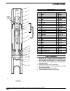
PUMP
DISASSEMBL
Y
NOTE: All threads are right hand.
CAUTION: DO NOT mar finish on (10) or (22) tube.
1. Clamp pump assembly in a vise on the air motor base assembly.
2. Place a strap wrench around (4) tube and loosen by turning counĆ
terclockwise. Ifthe wrenchslipsonthe (4)tube,wrapa pieceof400
sand paper around (4) tube and under strap wrench. (Note: Pipe
wrench will damage the finish of the tube.
3. After the (4) tube hasbeen pulled down toexpose the (2)rod, hold
air motor piston rodand unscrew the (2) rod fromthe air motor pisĆ
ton rod.
4. Remove the air motor assembly from the vise.
5. Vise the lower pump and remove (22) primer tube from (10) tube.
6. Remove (21) cotter pin, (20) primer, (19) seat, (18) washer, (17)
spacer, (16) body assembly (Disassemble body assembly if (14)
``u" cupor (15) spacerneeds tobe replaced.) and(12) washerfrom
assembly.
7. Remove (10) tube from (4) tube. Remove (5) gasket.
8. Pull rodassembly from(10) tubeanddisassemble (9)adapter from
(7) plunger to remove (8) ball.