


Page 8 of 8 6661AX-X-C
PN 97999-20
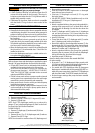
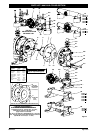
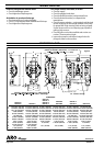
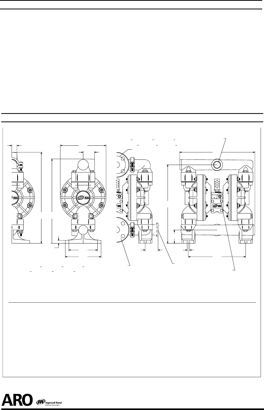
Dimensions shown are for reference only,they are shown in inches and millimeters (mm).
1/4 - 18 N.P.T. Air Inlet
May betapped for 1”pipe.
A
K
E
K
NBolt Circle
G
H
M
J
C
L
F F
B
D
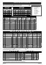
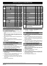
DIMENSIONS
6661XJ-X
6661X3-X
6661XP-X 6661X4-X 6661XT-X 6661XN-X 6661XR-X 6661XG-X
6661XL-X
6661XK-X
6661XS-X
6661XF-X
Inlet
Inlet
Outlet
Outlet
Figure 6
(6661X3-X, 6661X4-X, 6661XP-X) 1” A.N.S.I. Flange
A
B
C
D
E
F
G
H
J
K
L
M
N
12-21/32” (321 mm)
13-25/32” (349 mm)
10-1/16” (255 mm)
2-3/8” (60 mm)
8-1/16” (204 mm)
16” (406 mm)
5-1/32” (128 mm)
6-9/32” (160 mm)
7/16” (11 mm)
15/16” (23 mm)
2-9/32” (57 mm)
1/2” (13 mm)
3.140” (80 mm)
12-15/32” (316 mm)
13-19/32” (345 mm)
9-15/16” (252 mm)
2-11/32” (59 mm)
7-15/16” (201 mm)
15-25/32” (400 mm)
4-31/32” (126 mm)
6-7/32” (157 mm)
7/16” (11 mm)
29/32” (23 mm)
2-1/4” (56 mm)
1/2” (13 mm)
3.097” (79 mm)
13-1/32” (331 mm)
13-19/32” (345 mm)
9-15/16” (252 mm)
2-5/16” (59 mm)
7-15/16” (201 mm)
14-5/8” (371 mm)
4-31/32” (126 mm)
6-7/32” (157 mm)
7/16” (11 mm)
1-25/32” (50 mm)
1/2” (13 mm)
13-5/32” (334 mm)
13-25/32” (350 mm)
10-1/16” (255 mm)
2-11/32” (59 mm)
8-1/16” (204 mm)
16” (406 mm)
5-1/32” (128 mm)
6-9/32” (160 mm)
7/16” (11 mm)
1-1/32” (26 mm)
1/2” (13 mm)
3.140” (80 mm)
13-1/32 (331 mm)
13-19/32” (345 mm)
9-15/16” (252 mm)
2-5/16” (59 mm)
7-15/16” (201 mm)
15-25/32” (401 mm)
4-31/32” (126 mm)
6-7/32” (157 mm)
7/16” (11 mm)
1” (25 mm)
1/2” (13 mm)
3.097” (79 mm)
13-5/32” (334 mm)
13-25/32” (350 mm)
10-1/16” (255 mm)
2-11/32” (59 mm)
8-1/16” (204 mm)
14-13/16” (376 mm)
5-1/32” (128 mm)
6-9/32” (160 mm)
7/16” (11 mm)
2” (51 mm)
1/2” (13 mm)
(6661XF-X, 6661XG-X, 6661XR-X) 1” A.N.S.I. / DIN Flange
(6661XJ-X, 6661XK-X, 6661XS-X) 1 - 11-1/2 N.P.T.F. - 1
(6661XL-X, 6661XN-X, 6661XT-X) 1 - 11 BS Rp
TROUBLE SHOOTING
Product discharged from exhaust outlet.
Check for diaphragm rupture.
Check tightness of diaphragm nut.
Air bubbles in product discharge.
Check connections of suction plumbing.
Check “O” rings between intake manifold and uid caps.
Check tightness of diaphragm nut.
Low output volume, erratic ow, or no ow.
Check air supply.
Check for plugged outlet hose.
Check for kinked (restrictive) outlet material hose.
Check for kinked (restrictive) or collapsed inlet
material hose.
Check for pump cavitation − suction pipe should be sized
at least as large as the inlet thread diameter of the pump
for proper ow if high viscosity uids are being pumped.
Suction hose must be a non-collapsing type, capable of
pulling a high vacuum.
Check all joints on the inlet manifolds and suction con-
nections. These must be air tight.
Inspect the pump for solid objects lodged in the dia-
phragm chamber or the seat area.
DIMENSIONAL DATA