


66605X-X (en)Page 8 of 8
TROUBLE SHOOTING
Product discharged from air exhaust.
S Check for diaphragm rupture.
S Check tightness of (6) diaphragm nut.
Air Bubbles in Product Discharge.
S Check connections of suction plumbing.
S Check band clamps on intake manifold.
S Check “O” rings between intake manifold and fluid caps.
S Check tightness of (6) diaphragm nut.
Pump blows air out main exhaust when stalled on either stroke.
S Check “U” cups on (111) spool in major valve.
S Check (141) valve plate and (140) insert for wear.
S Check (103) sleeve and (2) “O” ring on diaphragm connecting rod.
S Check (119) “O” rings on (118) piston for wear.
Low output volume.
S Check air supply.
S Check for plugged outlet hose.
S For the pump to prime itself, it must be mounted in the vertical posi-
tion so that the balls will check by gravity.
S Check for pump cavitation -- suction pipeshouldbe 1/2” min. or larg-
er if high viscosity fluids are being pumped. Suction hose must be
non-collapsible type, capable of pulling a high vacuum.
S Check all joints onintake manifolds and suction connections.These
must be airtight.
S Check for sticking or improperly seating check valves.
S If pump cycles at a high rate or runs erratically, check (119) piston
“O” rings for wear.
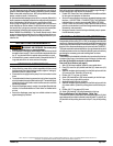
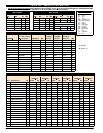
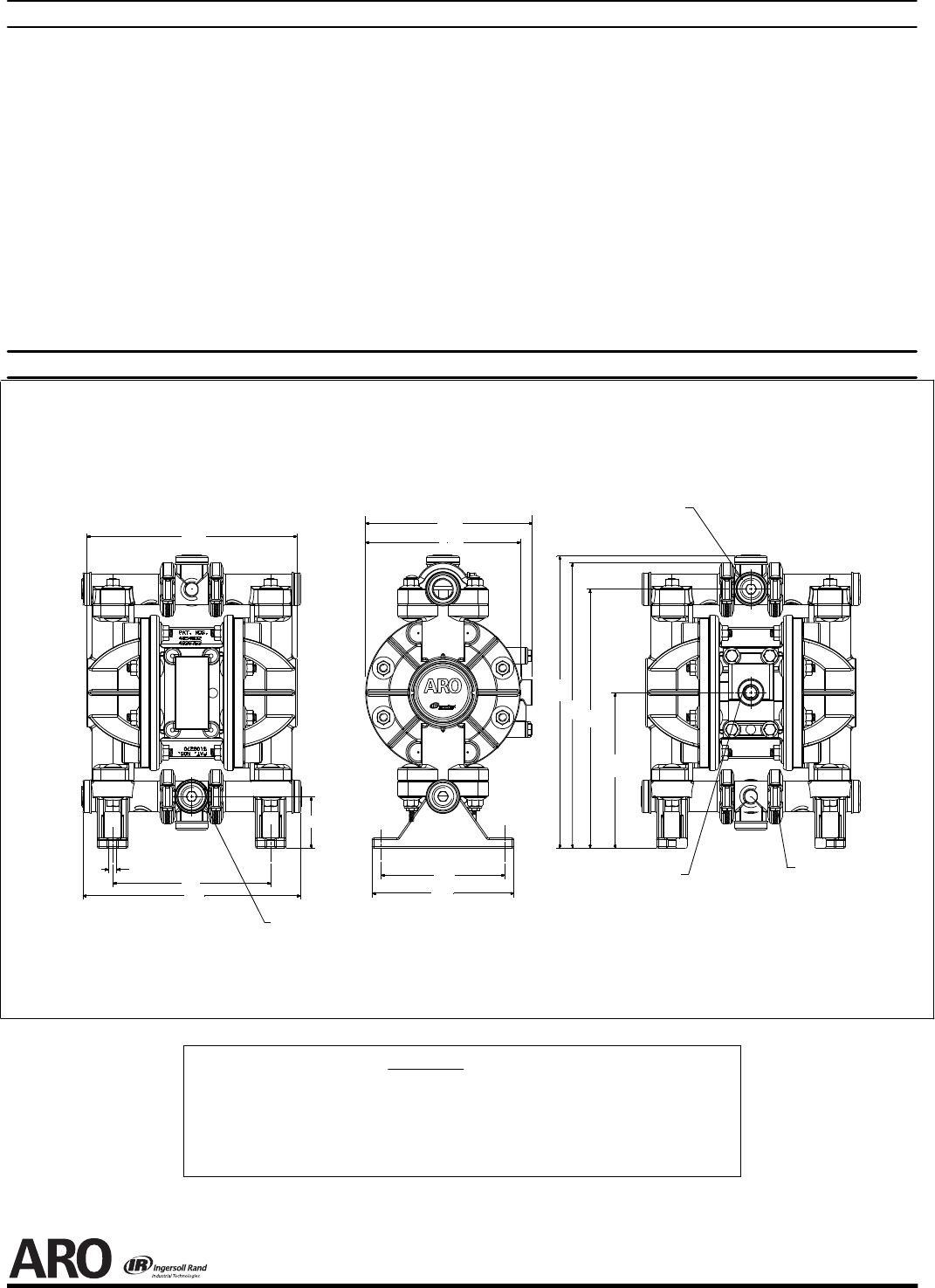
DIMENSIONAL DATA
PN 97999-99
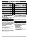
A - 8.155” (207.1 mm) E - 6.467” (164 mm) J - 8.445” (215 mm)
B - 10.051” (255 mm) F - 6.000” (152 mm) K - 0.312” (8 mm)
C - 6.135” (155.8 mm) G - 4.812” (122.2 mm) L - 11.331” (288 mm)
D - 2.005” (51 mm) H - 5.500” (140 mm) M - 11.084” (282 mm)
N - 6.040” (153 mm)
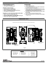
DIMENSIONS
Dimensions shown are for reference only, they are shown in inches and millimeters (mm).
1/2 - 14 N.P.T Material Outlet
Figure 4
1/4 - 18 N.P.T Air Inlet
NOTE: Loosening these
fasteners will allow Inlet /
Outlet to rotate
E
F
A
K
C
J
D
1/2 - 14 N.P.T
Material Inlet
G
H
N
B
M
L