


66605X-X (en)Page 6 of 8
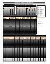
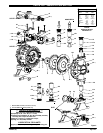
PARTS LIST / 66605X -X AIR MOTOR SECTION
n Indicates parts included in 637141 Air Section Repair Kit.
AIR SECTION PARTS
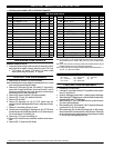
Item Description (size) Qty Part No. [Mtl] Item Description (size) Qty Part No. [Mtl]
101 Motor Body (1) 93091 [P]
n 102 “O” Ring (3/32” x 1” o.d.) (2) Y325-117 [B]
j 103 Sleeve (1) 93087 [Bz]
j 104 Snap Ring (13/16”) (2) 37285 [C]
111 Spool (1) 93085 [D]
118 Pilot Rod (1) 93088 [C]
n 119 “O” Ring (1/8” x 3/4” o.d.) (4) 93075 [U]
j 120 Spacer (3) 115959 [Z]
n 122 Snap Ring (1/2”) (2) 77802 [C]
124 Stud (5/16” - 18 x 1- 17/32”) ( see page 5) (8) 93249 [SS]
129 Muffler Assembly (1) 66972 [P]
129l Exhaust Cover (seenote 2) 93092 [PS]
n 130 Gasket (1) 93107 [SY]
131 Bolt (5/16” -18 x 1-1/4”) (8) 93095 [SS]
n 132 Gasket (see note 1) (1) 93339-1 [B]
133 Washer (9/32” i.d.) (4) 93096 [SS]
134 Bolt (1/4”-20x5”) (4) Y6-419-T [SS]
135 Valve Block (1) 93090 [P]
136 Plug (1) 93086 [D]
n 137 “O” Ring (3/32” x 1-1/2” o.d.) (1) Y325-125 [B]
n 138 Packing, “U” Cup (1/8” x 1” o.d.) (1) 94395 [U]
n 139 Packing, “U” Cup (1/8” x 1.427” o .d.) (1) 96383 [U]
n 140 Valve Insert (1) 93276 [CK]
n 141 Valve Plate (1) 93275 [CK]
142 Washer (2) 116038 [Z]
143 Plate (2) 93089 [SS]
201 Muffler (see note 2) 93110 [C]
n Key-Lube “O” Ring Lubricant 93706-1
10 Pack of Key-Lube 637175
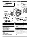
DIAPHRAGM PUMP SERVICE
GENERAL SERVICE NOTES:
S Inspect and replace old parts with new parts as necessary. Look for
deep scratches on metallic surfaces, and nicks or cuts in “O” rings.
S 7/16” wrench, 1/2” wrench, 7/16” socket, 1/2” socket, torque
wrench (measuring inch pounds), “O” ring pick.
FLUID SECTION DISASSEMBLY
1. Remove (34) top manifold / (36) swivel assembly.
Note: Manifold options involve single piece manifolds (60 / 61) or three
piece swivel type manifolds with clamps.
2. Remove (41) ball cages, (22) balls, (19 and 20) “O” rings and (21)
seats. Note: If cages are difficult to remove at this step, it may be
helpful to proceed through step 5 and remove them once they are
accessible from the inside of the fluid cap.
3. Remove (35) bottom manifolds / (36) swivel assembly.
4. Remove (19) “O” rings, (21) seats and (22) balls.
5. Remove (15) fluid caps.
6. Remove (6) diaphragm nut, (8) [(7) PTFE models only] dia-
phragm(s) and (5) diaphragm washer from (1) diaphragm connect-
ing rod.
7. Remove (1) connecting rod from air motor.
8. Carefully remove remaining (6) diaphragm nut, (8) [(7) PTFE mod-
els] diaphragm and (5) diaphragm washer from (1) connecting rod.
Do not mar surface of connecting rod.
9. Remove (2) “O” ring from connecting rod.
10. Remove (37) clamps from top and bottom manifold / swivel assem-
blies.
11. Remove (33) “O” rings from (36) swivels.
Note1:Partno.93339-1one-piecegasketreplacesthefollowingparts(notshown)inmod-
els manufactured prior to October 1988, Y325-10 (4), Y325-12, 93093, 93094,
Y325-8.
Note 2: The (129
l) exhaust cover and (201) muffler were standard until 9/92. They are
available separately for service or piped exhaust applications.
Note 3:A majorvalve service assemblyis availableseparately whichincludes items: 111,
132, 135 - 141. Order part no. 66362.
MATERIAL CODE
[B] = Nitrile [D] = Acetal [SY] = Syn-Seal
[Bz] = Bronze [P] = Polypropylene [U] = Polyurethane
[C] = Carbon Steel [PS] = Polyester [Z] = Zinc
[CK] = Ceramic [SS] = Stainless Steel
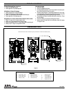
FLUID SECTION REASSEMBLY
S Reassemble in reverse order.
S Lubricate (1)connecting rodand (2)“O” ringwith Key-Lubeor equiv-
alent “O” ring lubricant.
S Install (5) diaphragm washers with i.d. chamfer toward diaphragm.
S When replacingPTFE diaphragms,install the93465 Santoprene di-
aphragm behind the PTFE diaphragm.
S When installing (41) cage, ball guides must line up with notches in
(21) seat to prevent damage.
S Before installing(35), (34)manifolds, (19) “O”ring should beproper-
ly seated on the o.d. of (41) ball cage.
S Before tightening (39) nut and (38) carriage bolts on (36) swivels,
attach the manifold / swivel assembly to the fluid caps. R otate (36)
swivel todesired positionand tighteneach of the nutsapproximately
8 - 9 turns, then finish tightening (29) nuts.
V “Smart Parts”, keep these items on hand in addition to the service kits for fast repair and reduction of down time.