iii
List of Figures
Figure GS.1: Minimum Logic and Power Connections ............................................................. 1-1
Part 1: Hardware Reference
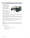
Figure 1.1.1: Microstepping MForce PowerDrive ...................................................................... 1-5
Figure 1.2.1: MForce PowerDrive
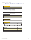
Mechanical Specifications ..................................................... 1-8
Figure 1.2.2: P1 — 12-Pin Locking Wire Crimp Pin Configuration ......................................... 1-9
Figure 1.2.3: P3 — 2-Pin Locking Wire Crimp Pin Configuration ......................................... 1-10
Figure 1.2.4: P4 — 4-Pin Locking Wire Crimp Pin Configuration ......................................... 1-10
Part 2: Connecting and Interfacing
Figure 2.1.1: Base Mounting the MForce PowerDrive ...................................................................3
Figure 2.1.2: End Mounting the MForce PowerDrive ...................................................................4
Figure 2.2.1: IMS ISP300 Switch Mode Power Supply ..................................................................7
Figure 2.2.2: MForce PowerDrive DC Power Connection .............................................................9
Figure 2.2.3: DC Cabling - Under 50 Feet ....................................................................................9
Figure 2.2.4: AC To Full Wave Bridge Rectifier, Cabling over 50 Feet .........................................10
Figure 2.2.5: AC Cabling - 50 Feet or Greater - AC To Power Supply .........................................10
Figure 2.3.1 A & B: Per Phase Winding Inductance ....................................................................12
Figure 2.3.2: 8 Lead Motor Series Connections ...........................................................................14
Figure 2.3.3: 8 Lead Motor Parallel Connections........................................................................14
Figure 2.3.4: 6 Lead Half Coil (Higher Speed) Motor Connections ...........................................15
Figure 2.3.5: 6 Lead Half Coil (Higher Speed) Motor Connections ...........................................15
Figure 2.3.6: 4 Lead Motor Connections .....................................................................................16
Figure 2.3.7: Motor Cabling Less than 50 Feet ............................................................................16
Figure 2.3.8: Motor Cableing Greater than 50 Feet .....................................................................17
Figure 2.4.1: Isolated Logic Pins and Connections ......................................................................19
Figure 2.4.2: Input Clock Functions ...........................................................................................20
Figure 2.4.3: Clock Input Timing Characteristics ........................................................................21
Figure 2.4.4: Optocoupler Input Circuit Diagram .......................................................................22
Figure 2.4.5: Open Collector Interface Example ..........................................................................23
Figure 2.4.6: Switch Interface Example .......................................................................................24
Figure 2.4.7: Minimum Required Connections ...........................................................................25
Figure 2.5.1: MD-CC300-000 Parameter Setup Cable ................................................................26
Figure 2.5.2: SPI Pins and Connections, 12-Pin Wire Crimp ......................................................27
Figure 2.5.3: Logic Level Shifting and Conditioning Circuit .......................................................27
Figure 2.5.4: SPI Master with a Single Microstepping MForce PowerDrive .................................28
Figure 2.5.5: SPI Master with Multiple Microstepping MForce PowerDrives ..............................28
Figure 2.6.1: SPI Motor Interface Color Coding .........................................................................30
Figure 2.6.2: SPI Motor Interface File Menu ...............................................................................30
Figure 2.6.3: SPI Motor Interface View Menu .............................................................................30
Figure 2.6.4: SPI Motor Interface Recall Menu ...........................................................................31
Figure 2.6.5: SPI Motor Interface Upgrade Menu .......................................................................31
Figure 2.6.6: SPI Motor Interface Help Menu and About Screen ................................................31
Figure 2.6.7: SPI Motor Interface Motion Settings Screen ...........................................................32
Figure 2.6.8: SPI Motor Interface I/O Settings Screen .................................................................34
Figure 2.6.9: SPI Motor Interface Part and Serial Number Screen ...............................................35
Figure 2.6.10: SPI Motor Interface Upgrade Utility ....................................................................36
Figure 2.6.11: SPI Motor Interface Initialization .........................................................................37
Figure 2.6.12: SPI Motor Interface Port Menu ............................................................................37
Figure 2.7.1: SPI Timing .............................................................................................................38
Figure 2.7.2: Read/Write Byte Order for Parameter Settings (Default Parameters Shown) ...........40
Figure 2.6.13: Motor Settings Screen...........................................................................................38
Figure 2.6.14: PWM Mask Bits ...................................................................................................38
Figure 2.6.15: PWM Frequency Range ......................................................................................39
Figure 2.6.16: PWM Control Bits ...............................................................................................40
Figure 2.7.1: SPI Timing .............................................................................................................41
Figure 2.7.2: Read/Write Byte Order for Parameter Settings (Default Parameters Shown) ...........43


