


7
45062-01 • 07/01/09 • Hunter Fan Company
CAUTION: e remote control device complies with part 15 of the FCC rules.
Changes or modications not expressly approved by Hunter Fan Company could void
your authority to operate this equipment.
Operation is subject to the following two conditions:
1. is device may not cause harmful interference.
2. is device must accept any interference received, including interference that may
cause undesired operation.
WARNING: Use only the Hunter Fan speed control supplied with this fan.
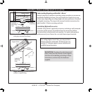
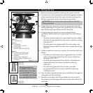
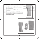
4-1. IMPORTANT! Before you change the DIP switch settings, make
sure the battery is not connected to the transmitter.
Change the position of the DIP switches in the remote transmitter
and the receiver. Make sure that the DIP switches match in
the remote receiver and transmitter. If they don’t match, the
transmitter will not function.
4-2. ere is a toggle switch beside the DIP switches on the transmitter.
Move the toggle switch toward the side that reads “CFL” if you are
going to operate the fan with CFL bulbs. Move the switch to the
“INC” side if you are going to use incandescent bulbs.
4-3. Install the included 9-volt battery into the transmitter.
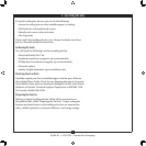
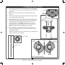
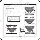
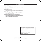
Setting DIP switches
When two or more fans are located near each other, you may desire
to have the receiver/transmitter for each fan set to a dierent code,
so that the operation of one fan does not aect the operation of the
other fans.
e DIP switches for the receiver are located on the at surface of
the receiver. e DIP switches for the transmitter are in the battery
compartment.
Receiver DIP
switches
Transmitter DIP switches
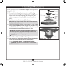
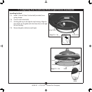
4-4. Raise the fan and align the slots in the canopy with the hooks
on the ceiling plate.
Note: To hang the fan, you must tilt the canopy to an almost
vertical position so that the canopy slots sit on the ceiling
plate hooks.
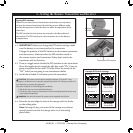
CFL INC
Dip Switches
Set to 01110
Dip Switches
Set to 01001
Dip Switches
Set to 01110
Dip Switches
Set to 01001
Receiver 1
Receiver 2
Transmitter 2Transmitter 1
Example DIP Switch Settings
DIP Switches
Set to 0111
DIP Switches
Set to 0100
DIP Switches
Set to 0100
DIP Switches
Set to 0111
4 • Setting the Remote Transmitter and Receiver