


5
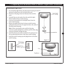
2-1. Drill two pilot holes into the wood support structure through the
outermost holes in the outlet box. e pilot holes should be 9/64”
in diameter.
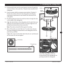
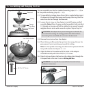
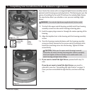
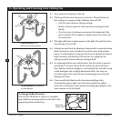
2-2. Your fan comes with four neoprene noise isolators (“Isolators”).
Position the isolators between the ceiling plate and ceiling by
inserting the raised areas on each isolator into the holes in the
ceiling plate.
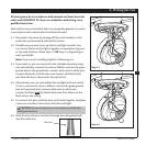
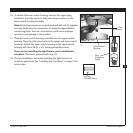
2-3. read the lead wires from the outlet box down through the hole
in the middle of the ceiling plate.
2-4. Align the slotted holes in the ceiling plate with the pilot holes you
drilled in the wood support structure. For proper alignment use
slotted holes directly across from each other.
Note: e isolators should be flush against the ceiling.
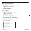
2-5. Place a flat washer on each of the two 3” wood screws and pass
the screws through the slotted holes in the ceiling plate into the
pilot holes you drilled.
Tighten the screws into the 9/64” pilot holes; do not use lubricants
on the screws. Do not over tighten.
Step 2-2
Flat Washer
3” Wood Screw
Steps 2-3 – 2-5
2 • Installing the Ceiling Plat e
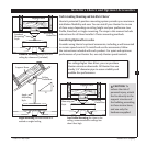
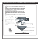
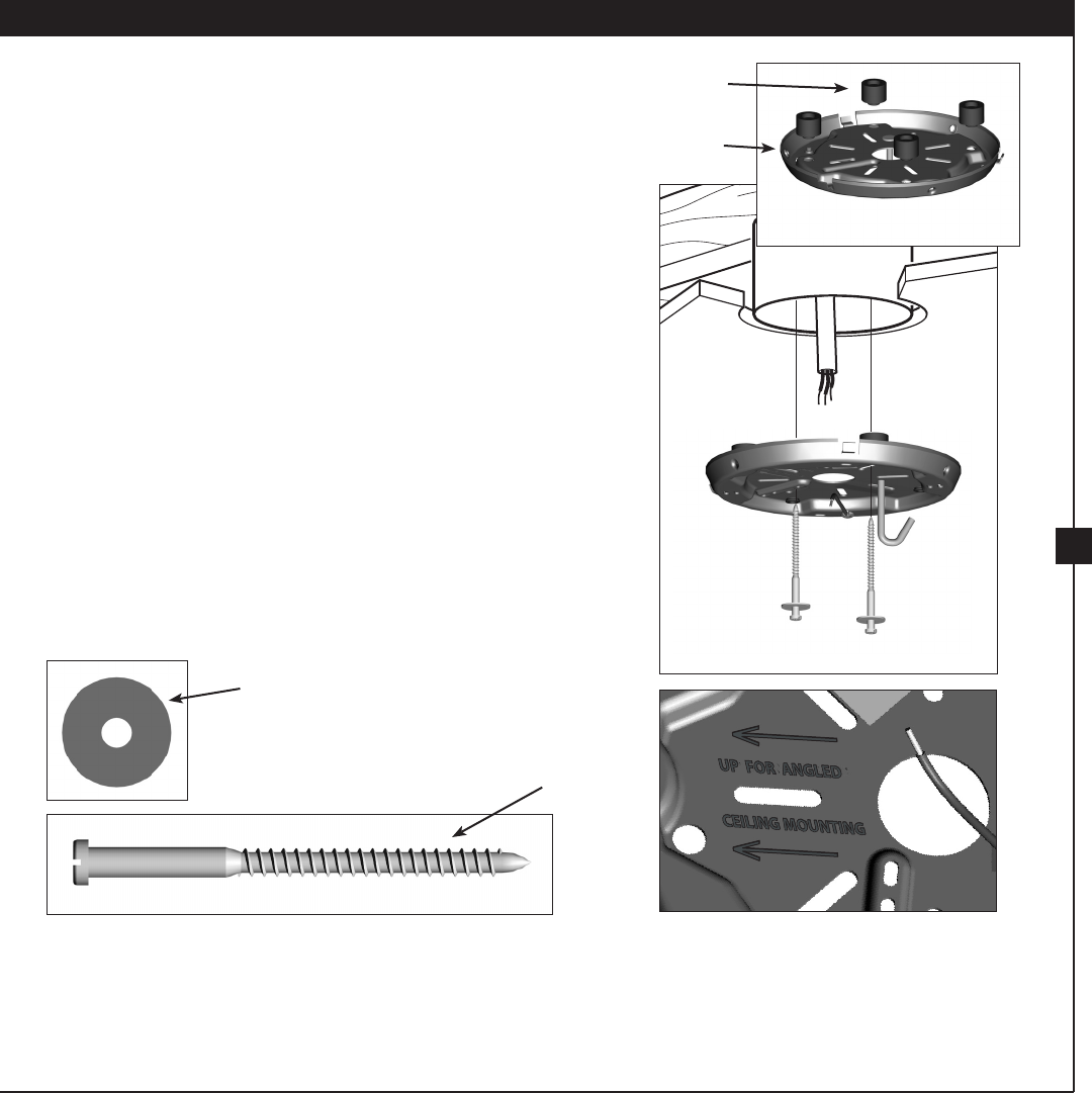
For Angled Ceilings: Be sure to
orient the ceiling plate so that the
arrows printed on the ceiling plate are
pointing towards the ceiling peak.
Ceiling
Plate
Isolator
41931-01 • 04/14/07 Hunter Fan Company