


41814-01 01/14/2003 © 2003 Hunter Fan Company
88
88
8
FF
FF
F
ii
ii
i
gg
gg
g
urur
urur
ur
e 24 - Ae 24 - A
e 24 - Ae 24 - A
e 24 - A
tt
tt
t
tt
tt
t
aa
aa
a
cc
cc
c
hh
hh
h
inin
inin
in
g tg t
g tg t
g t
hh
hh
h
e be b
e be b
e b
ll
ll
l
aa
aa
a
dd
dd
d
e te t
e te t
e t
o to t
o to t
o t
hh
hh
h
e be b
e be b
e b
ll
ll
l
aa
aa
a
dd
dd
d
e ire ir
e ire ir
e ir
oo
oo
o
n an a
n an a
n a
nn
nn
n
dd
dd
d
mm
mm
m
ee
ee
e
dd
dd
d
aa
aa
a
llilli
llilli
lli
oo
oo
o
nn
nn
n
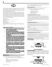
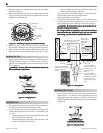
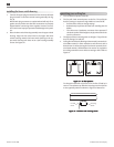
If you used grommets, the blades may appear slightly loose
after screws are tightened. This is normal.
3. Remove the blade mounting screws and rubber shipping
bumpers from the motor.
4. For each blade, insert one blade mounting screw through the
blade iron as shown in Figure 25, and attach lightly to the fan.
Insert the second blade mounting screw, then securely tighten
both mounting screws.
FF
FF
F
ii
ii
i
gg
gg
g
urur
urur
ur
e 25 - Ae 25 - A
e 25 - Ae 25 - A
e 25 - A
tt
tt
t
tt
tt
t
aa
aa
a
cc
cc
c
hh
hh
h
inin
inin
in
g tg t
g tg t
g t
hh
hh
h
e be b
e be b
e b
ll
ll
l
aa
aa
a
dd
dd
d
e ire ir
e ire ir
e ir
oo
oo
o
n tn t
n tn t
n t
o to t
o to t
o t
hh
hh
h
e fe f
e fe f
e f
aa
aa
a
nn
nn
n
installing the light fixture
You can install with or without the light fixture. If you want to
install without the light fixture, skip to the
inin
inin
in
ss
ss
s
tt
tt
t
aa
aa
a
llinllin
llinllin
llin
g wg w
g wg w
g w
ii
ii
i
tt
tt
t
hh
hh
h
oo
oo
o
uu
uu
u
t tt t
t tt t
t t
hh
hh
h
ee
ee
e
lili
lili
li
gg
gg
g
hh
hh
h
t ft f
t ft f
t f
ii
ii
i
xx
xx
x
tt
tt
t
urur
urur
ur
ee
ee
e section.
WW
WW
W
AA
AA
A
RR
RR
R
NN
NN
N
II
II
I
NN
NN
N
G: UsG: Us
G: UsG: Us
G: Us
e oe o
e oe o
e o
nlnl
nlnl
nl
y ty t
y ty t
y t
hh
hh
h
e se s
e se s
e s
upup
upup
up
pp
pp
p
lili
lili
li
ee
ee
e
d lid li
d lid li
d li
gg
gg
g
hh
hh
h
t ft f
t ft f
t f
ii
ii
i
xx
xx
x
tt
tt
t
urur
urur
ur
e fe f
e fe f
e f
oo
oo
o
r tr t
r tr t
r t
hh
hh
h
ii
ii
i
s fs f
s fs f
s f
aa
aa
a
nn
nn
n
mm
mm
m
oo
oo
o
dd
dd
d
ee
ee
e
l.l.
l.l.
l.
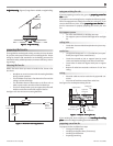
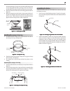
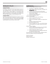
attaching the upper switch housing
1. Partially install two #6-32 x 3/8" housing assembly screws into
the switch housing mounting plate as shown in Figure 26.
2. Feed the upper plug connector through the center opening of
the upper switch housing. See Figure 26.
FF
FF
F
ii
ii
i
gg
gg
g
urur
urur
ur
e 26 - Ae 26 - A
e 26 - Ae 26 - A
e 26 - A
tt
tt
t
tt
tt
t
aa
aa
a
cc
cc
c
hh
hh
h
inin
inin
in
g tg t
g tg t
g t
hh
hh
h
e upe up
e upe up
e up
pp
pp
p
ee
ee
e
r sr s
r sr s
r s
ww
ww
w
ii
ii
i
tt
tt
t
cc
cc
c
h hh h
h hh h
h h
oo
oo
o
uu
uu
u
sinsin
sinsin
sin
g tg t
g tg t
g t
o to t
o to t
o t
hh
hh
h
ee
ee
e
mm
mm
m
oo
oo
o
unun
unun
un
tt
tt
t
inin
inin
in
g pg p
g pg p
g p
ll
ll
l
aa
aa
a
tt
tt
t
ee
ee
e
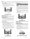
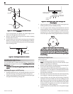
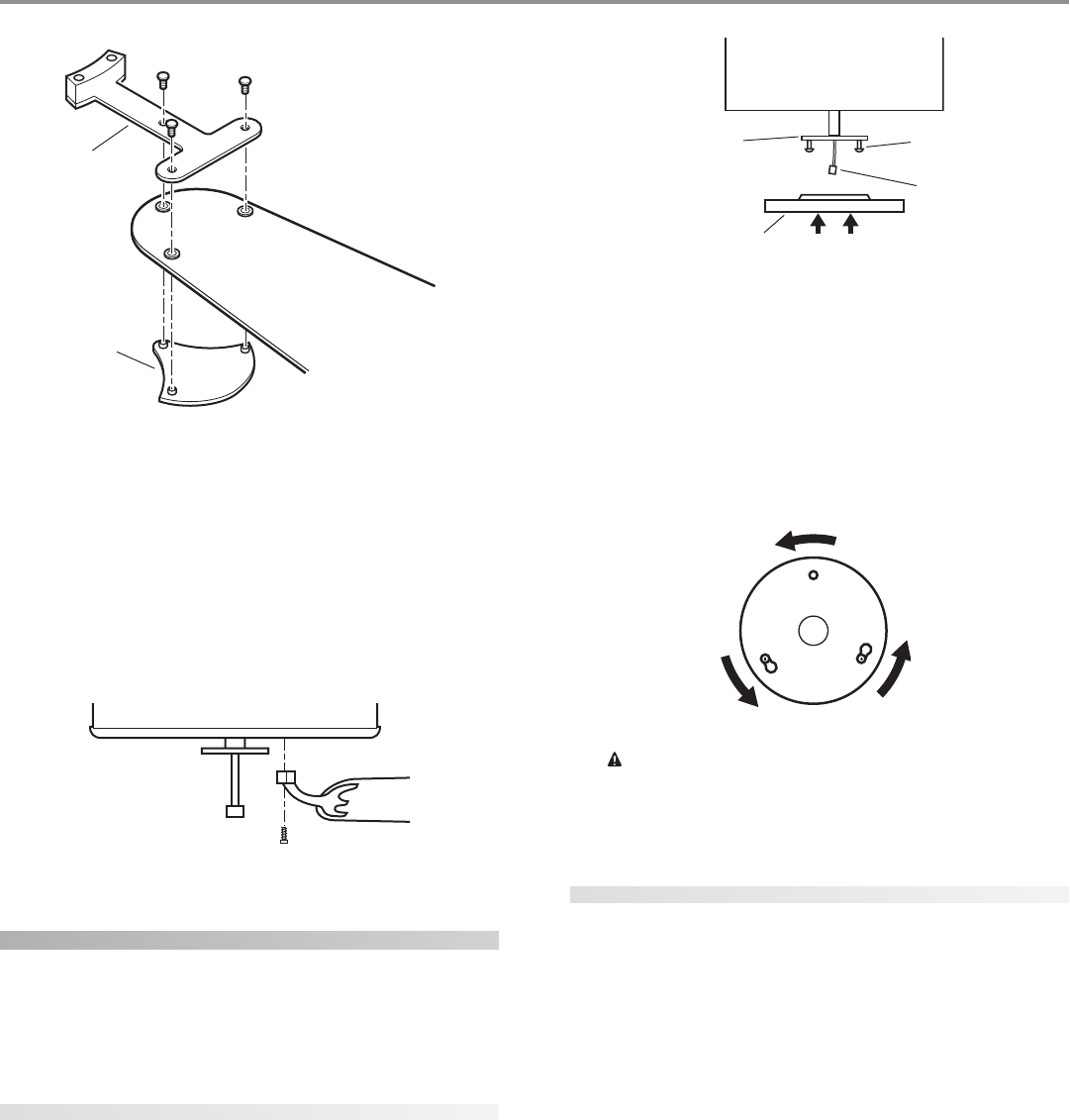
3. Align the keyhole slots in the upper switch housing with the
housing assembly screws installed previously.
4. Turn the upper switch housing counterclockwise until the
housing assembly screws are firmly situated in the narrow end
of the keyhole slots as shown in Figure 27. Install the one re-
maining #6-32 x 3/8" housing assembly screw into the third
hole in the upper switch housing. Tighten all three screws firmly.
FF
FF
F
ii
ii
i
gg
gg
g
urur
urur
ur
e 27 - Me 27 - M
e 27 - Me 27 - M
e 27 - M
oo
oo
o
unun
unun
un
tt
tt
t
inin
inin
in
g tg t
g tg t
g t
hh
hh
h
e upe up
e upe up
e up
pp
pp
p
ee
ee
e
r sr s
r sr s
r s
ww
ww
w
ii
ii
i
tt
tt
t
cc
cc
c
h hh h
h hh h
h h
oo
oo
o
uu
uu
u
sinsin
sinsin
sin
gg
gg
g
CC
CC
C
AA
AA
A
UU
UU
U
TT
TT
T
II
II
I
OO
OO
O
N: MN: M
N: MN: M
N: M
aa
aa
a
kk
kk
k
e se s
e se s
e s
urur
urur
ur
e te t
e te t
e t
hh
hh
h
e upe up
e upe up
e up
pp
pp
p
ee
ee
e
r sr s
r sr s
r s
ww
ww
w
ii
ii
i
tt
tt
t
cc
cc
c
h hh h
h hh h
h h
oo
oo
o
uu
uu
u
sinsin
sinsin
sin
g ig i
g ig i
g i
s ss s
s ss s
s s
e-e-
e-e-
e-
cc
cc
c
urur
urur
ur
ee
ee
e
ll
ll
l
y ay a
y ay a
y a
tt
tt
t
tt
tt
t
aa
aa
a
cc
cc
c
hh
hh
h
ee
ee
e
d td t
d td t
d t
o to t
o to t
o t
hh
hh
h
e se s
e se s
e s
ww
ww
w
ii
ii
i
tt
tt
t
cc
cc
c
h hh h
h hh h
h h
oo
oo
o
uu
uu
u
sinsin
sinsin
sin
g mg m
g mg m
g m
oo
oo
o
unun
unun
un
tt
tt
t
inin
inin
in
g pg p
g pg p
g p
ll
ll
l
aa
aa
a
tt
tt
t
ee
ee
e
. F. F
. F. F
. F
aa
aa
a
il-il-
il-il-
il-
urur
urur
ur
e te t
e te t
e t
o po p
o po p
o p
rr
rr
r
oo
oo
o
pp
pp
p
ee
ee
e
rr
rr
r
ll
ll
l
y ay a
y ay a
y a
tt
tt
t
tt
tt
t
aa
aa
a
cc
cc
c
h ah a
h ah a
h a
nn
nn
n
d td t
d td t
d t
ii
ii
i
gg
gg
g
hh
hh
h
tt
tt
t
ee
ee
e
n an a
n an a
n a
ll tll t
ll tll t
ll t
hrhr
hrhr
hr
ee
ee
e
e he h
e he h
e h
oo
oo
o
uu
uu
u
sinsin
sinsin
sin
g ag a
g ag a
g a
ss
ss
s
--
--
-
ss
ss
s
ee
ee
e
mbmb
mbmb
mb
ll
ll
l
y sy s
y sy s
y s
cc
cc
c
rr
rr
r
ee
ee
e
ww
ww
w
s cs c
s cs c
s c
oo
oo
o
ulul
ulul
ul
d rd r
d rd r
d r
ee
ee
e
ss
ss
s
ulul
ulul
ul
t in tt in t
t in tt in t
t in t
hh
hh
h
e se s
e se s
e s
ww
ww
w
ii
ii
i
tt
tt
t
cc
cc
c
h hh h
h hh h
h h
oo
oo
o
uu
uu
u
sinsin
sinsin
sin
g ag a
g ag a
g a
nn
nn
n
d lid li
d lid li
d li
gg
gg
g
hh
hh
h
tt
tt
t
ff
ff
f
ii
ii
i
xx
xx
x
tt
tt
t
urur
urur
ur
e fe f
e fe f
e f
aa
aa
a
llinllin
llinllin
llin
gg
gg
g
..
..
.
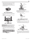
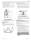
attaching the light fixture
Refer to Figure 28.
1. Remove the plug cap from the lower switch housing.
NN
NN
N
oo
oo
o
tt
tt
t
e:e:
e:e:
e: Do not discard the plug cap. You will need this if you
remove the light fixture in the future.
2. Remove top housing from the light fixture by loosening the
three screws and turning counter clockwise.
3. Locate the two wires in the lower switch housing labeled “Con-
nect Light Here” or “For Light Use”. One will be white, the other
black/white. Unscrew the wire nuts counterclockwise to ex-
pose the bare metal leads.
4. Place these wires into the hole in the center of the top housing
for the light kit. Slide the top housing over the two wires.
5. Screw the fixture into the lower switch housing. Thread the
lockwasher and nut provided over the wires. Making sure the
light fixture mounting screw holes are aligned; hold the light
fixture and tighten the nut on the inside of the lower switch
housing. Insert and tighten the two #6-32 sems light fixture
mounting screws. Refer to Figure 28.
6. Locate the white wire and the black wire coming from the light
fixture.
Blade Iron
Medallion
Switch Housing
Mounting Plate
Upper Switch
Housing
Housing
Assembly
Screw
Upper Plug
Connector