


41814-01 01/14/2003 © 2003 Hunter Fan Company
66
66
6
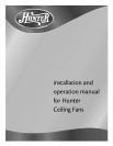
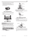
6. Place the canopy trim ring then the canopy over the adapter
as shown in Figure 15.
7. Place the low profile washer (lip up) into the canopy as shown
in Figure 15 fitting the notch in the low profile washer over the
adapter set screw and hook.
FF
FF
F
ii
ii
i
gg
gg
g
urur
urur
ur
e 15 - Ae 15 - A
e 15 - Ae 15 - A
e 15 - A
ss
ss
s
ss
ss
s
ee
ee
e
mbmb
mbmb
mb
linlin
linlin
lin
g cg c
g cg c
g c
aa
aa
a
nn
nn
n
oo
oo
o
pp
pp
p
y fy f
y fy f
y f
oo
oo
o
r lr l
r lr l
r l
oo
oo
o
w pw p
w pw p
w p
rr
rr
r
oo
oo
o
ff
ff
f
ilil
ilil
il
e me m
e me m
e m
oo
oo
o
unun
unun
un
tt
tt
t
inin
inin
in
gg
gg
g
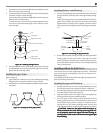
8. Rotate the canopy until the arrow on the low profile washer
aligns with the tab hole on the canopy as shown in Figure 15.
9. Align the holes in the low profile washer with the holes in the
adapter and assemble securely with the three #8-32 x 1” screws.
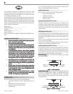
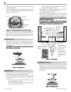
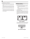
hanging the fan
1. Raise the fan and place the hook through the loop on the ceil-
ing plate as shown in Figure 16. Use the note and arrow en-
graved in the ceiling plate to assist in determining the direc-
tion to assemble.
WW
WW
W
AA
AA
A
RR
RR
R
NN
NN
N
II
II
I
NN
NN
N
G: FG: F
G: FG: F
G: F
aa
aa
a
n mn m
n mn m
n m
aa
aa
a
y fy f
y fy f
y f
aa
aa
a
ll ill i
ll ill i
ll i
f nf n
f nf n
f n
oo
oo
o
t at a
t at a
t a
ss
ss
s
ss
ss
s
ee
ee
e
mbmb
mbmb
mb
ll
ll
l
ee
ee
e
d ad a
d ad a
d a
s dirs dir
s dirs dir
s dir
ee
ee
e
cc
cc
c
tt
tt
t
ee
ee
e
d ind in
d ind in
d in
tt
tt
t
hh
hh
h
ee
ee
e
ss
ss
s
e ine in
e ine in
e in
ss
ss
s
tt
tt
t
aa
aa
a
llll
llll
ll
aa
aa
a
tt
tt
t
ii
ii
i
oo
oo
o
n inn in
n inn in
n in
ss
ss
s
tt
tt
t
rr
rr
r
uu
uu
u
cc
cc
c
tt
tt
t
ii
ii
i
oo
oo
o
nn
nn
n
ss
ss
s
..
..
.
FF
FF
F
ii
ii
i
gg
gg
g
urur
urur
ur
e 16 - Hae 16 - Ha
e 16 - Hae 16 - Ha
e 16 - Ha
nn
nn
n
gg
gg
g
inin
inin
in
g tg t
g tg t
g t
hh
hh
h
e fe f
e fe f
e f
aa
aa
a
nn
nn
n
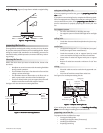
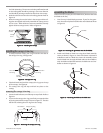
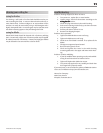
wiring the fan
1. Disconnect the power by turning off the circuit breakers to
the outlet box and associated wall switch location.
2. You can use either one or two wall switches to control the fan
and/or lights separately. Use connection 1, as described in Fig-
ure 17, to
• control the light with a wall switch and the fan with a pull
chain (one wall switch required),
• control the light with a pull chain and the fan with a wall
switch (one wall switch required), or
• control the light with one wall switch and the fan with
another (two wall switches required).
Use connection 2, as described in Figure 17, if there is no sepa-
rate wall switch power wire for the light fixture.
NOTE: Wall switches not included.
3. Connect the wires as shown in Figure 17. To connect the wires,
twist the bare metal leads together. Place a wire nut over the
intertwined length of wire and twist clockwise until tight as.
CC
CC
C
AA
AA
A
UU
UU
U
TT
TT
T
II
II
I
OO
OO
O
N: BN: B
N: BN: B
N: B
e se s
e se s
e s
urur
urur
ur
e ne n
e ne n
e n
o bo b
o bo b
o b
aa
aa
a
rr
rr
r
e we w
e we w
e w
irir
irir
ir
e oe o
e oe o
e o
r wr w
r wr w
r w
irir
irir
ir
e se s
e se s
e s
tt
tt
t
rr
rr
r
aa
aa
a
nn
nn
n
dd
dd
d
s as a
s as a
s a
rr
rr
r
e ve v
e ve v
e v
ii
ii
i
ss
ss
s
--
--
-
ibib
ibib
ib
ll
ll
l
e ae a
e ae a
e a
ff
ff
f
tt
tt
t
ee
ee
e
r mr m
r mr m
r m
aa
aa
a
kk
kk
k
inin
inin
in
g cg c
g cg c
g c
oo
oo
o
nnnn
nnnn
nn
ee
ee
e
cc
cc
c
tt
tt
t
ii
ii
i
oo
oo
o
nn
nn
n
ss
ss
s
..
..
.
AA
AA
A
ll wll w
ll wll w
ll w
irir
irir
ir
inin
inin
in
g mug mu
g mug mu
g mu
ss
ss
s
t bt b
t bt b
t b
e in ae in a
e in ae in a
e in a
cc
cc
c
cc
cc
c
oo
oo
o
rr
rr
r
dd
dd
d
aa
aa
a
nn
nn
n
cc
cc
c
e we w
e we w
e w
ii
ii
i
tt
tt
t
h nh n
h nh n
h n
aa
aa
a
tt
tt
t
ii
ii
i
oo
oo
o
nn
nn
n
aa
aa
a
l al a
l al a
l a
nn
nn
n
d ld l
d ld l
d l
oo
oo
o
cc
cc
c
aa
aa
a
ll
ll
l
ee
ee
e
ll
ll
l
ee
ee
e
cc
cc
c
tt
tt
t
rr
rr
r
ii
ii
i
cc
cc
c
aa
aa
a
l cl c
l cl c
l c
oo
oo
o
dd
dd
d
ee
ee
e
s as a
s as a
s a
nn
nn
n
d Ad A
d Ad A
d A
NN
NN
N
SS
SS
S
I/NI/N
I/NI/N
I/N
FF
FF
F
PP
PP
P
A 70. IA 70. I
A 70. IA 70. I
A 70. I
f yf y
f yf y
f y
oo
oo
o
u au a
u au a
u a
rr
rr
r
e une un
e une un
e un
ff
ff
f
aa
aa
a
mm
mm
m
iliili
iliili
ili
aa
aa
a
rr
rr
r
ww
ww
w
ii
ii
i
tt
tt
t
h wh w
h wh w
h w
irir
irir
ir
inin
inin
in
gg
gg
g
, y, y
, y, y
, y
oo
oo
o
u su s
u su s
u s
hh
hh
h
oo
oo
o
ulul
ulul
ul
d ud u
d ud u
d u
ss
ss
s
e a qe a q
e a qe a q
e a q
uu
uu
u
aa
aa
a
lili
lili
li
ff
ff
f
ii
ii
i
ee
ee
e
d ed e
d ed e
d e
ll
ll
l
ee
ee
e
cc
cc
c
tt
tt
t
rr
rr
r
ii
ii
i
cc
cc
c
ii
ii
i
aa
aa
a
nn
nn
n
..
..
.
FF
FF
F
ii
ii
i
gg
gg
g
urur
urur
ur
e 17 - We 17 - W
e 17 - We 17 - W
e 17 - W
irir
irir
ir
inin
inin
in
g tg t
g tg t
g t
hh
hh
h
e fe f
e fe f
e f
aa
aa
a
nn
nn
n
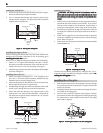
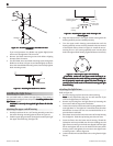
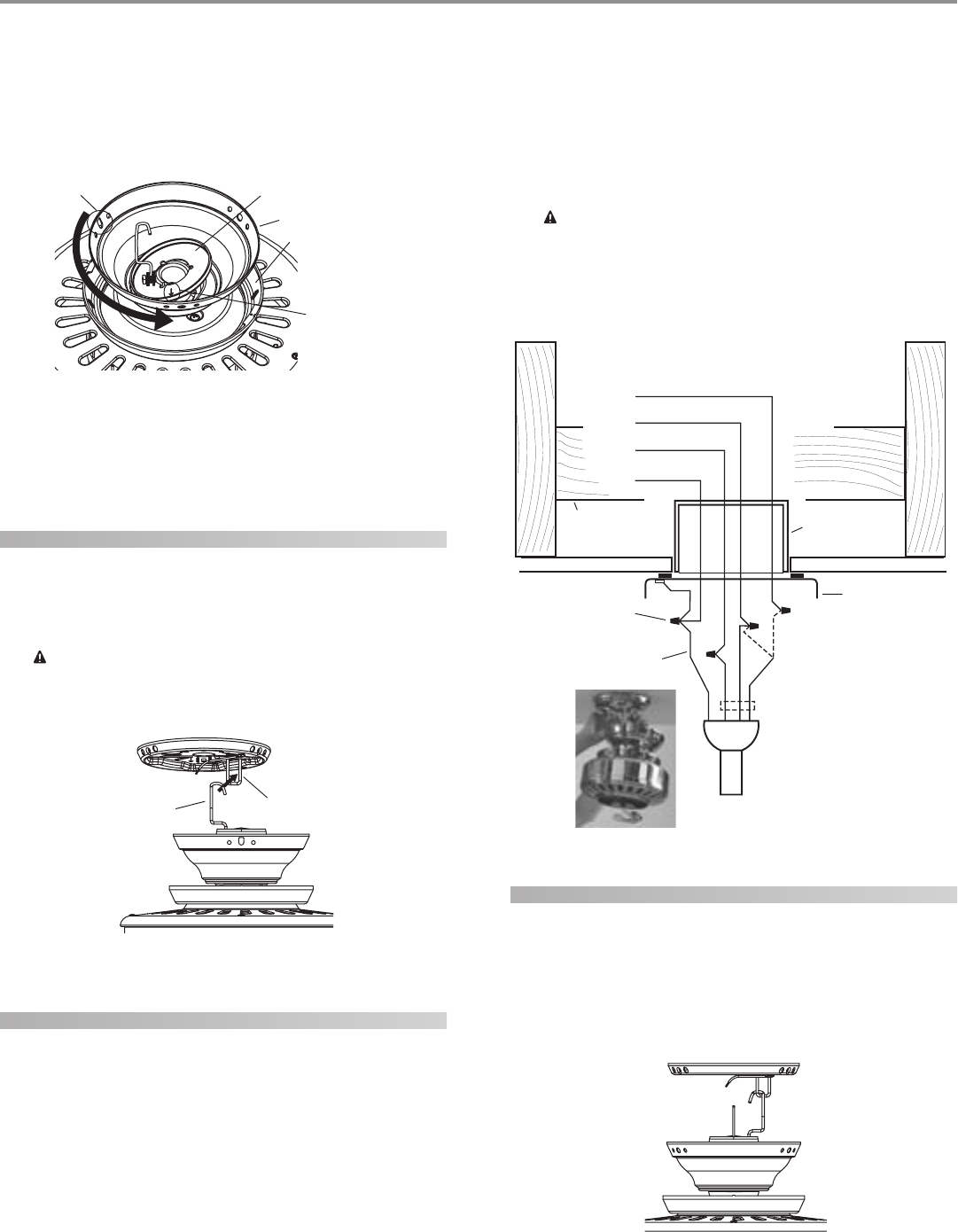
installing the canopy
1. Rotate the fan 180º clockwise from the initial position when
hanging the fan. The arrows on the hanger ball and on the
ceiling plate should be pointing in the same direction and
should be pointing towards the tab hole on the canopy. Refer
to Figure 18.
FF
FF
F
ii
ii
i
gg
gg
g
urur
urur
ur
e 18 - Re 18 - R
e 18 - Re 18 - R
e 18 - R
oo
oo
o
tt
tt
t
aa
aa
a
tt
tt
t
inin
inin
in
g tg t
g tg t
g t
hh
hh
h
e fe f
e fe f
e f
aa
aa
a
nn
nn
n
Hook
Loop
Canopy Trim Ring
Arrow on the
Low Profile
Washer
Low Profile Washer
Canopy
Tab Hole
Wall Switch Wire for Separate
Control of Light Fixture
(Note: Wall
switch must be
acceptable as a
general-use
switch.)
Power
Wires
in
Ceiling
Black
White
Bare or Green
2 x 4 Brace
Outlet Box
Ceiling Plate
Approved
Connectors
Green Ground Wire from
Hanger Pipe (not present
with flush mounting
option)
Connections:
1. Connect Blk/Wht
wire from the fan to the
wall switch for separate
control of the light
fixture, or
2. Connect Blk/Wht
wire from the fan to the
ceiling black wire if there
is no separate wall
switch wire for the light
fixture.
Blk/Wht
3 Wires
from Fan
White
Black
1
2