


41973-01 03/08/2006 9
ENGLISH
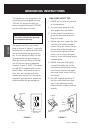
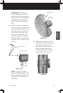
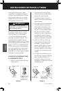
FIGURE 13
Fan
Motor
Hole in motor face
Interlock Bracket
FIGURE 12A
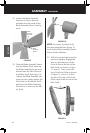
26. Align the two ends of the Inter-
lock Bracket with the two notches
in the tab on top of the Front
Grille. Press the two ends of the
Interlock Bracket into the two
notches of the tab on the top of
the Front Grille. See Figure 13.
Interlock Bracket
Hole in
motor face
FIGURE 12B
note: For clarity, the Back
Grille and Blade Assembly have
been removed from Figure 12A
to show the Interlock Bracket
installation.
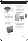
Attention:
This fan has a
built-in safety switch that will
not allow the fan to operate un-
less the Grille is fully assembled
to the Motor Face and the In-
terlock Bracket is secured into
place.
25. Install the Interlock Bracket by
tilting it as shown in Figure 12A
and inserting the bottom of the
Interlock Bracket into the hole
on the top of the Motor Face
as shown in Figure 12B. Then
move the top of the Interlock
Bracket forward over the front
and Back Grille as shown in Fig-
ure 12b.