


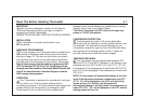
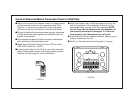
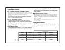
■ Each wire coming from the wall to the existing thermostat is
connected to a terminal point on that thermostat. Each of these
terminal points is usually marked with a code letter as shown in
Table A on this page.
■ The number of wires in your system can be as few as two (for
heat only systems), as many as eight, or any number in between.
If you follow the labeling procedures correctly, you do not have to
be concerned about how many wires there are.
■ There is often no terminal marking on the existing thermostat of two
wire, heat only systems. Just connect either of the wires to the RH
terminal, then connect the other wire to the W terminal to complete
the circuit.
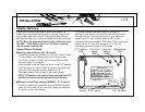
■ IMPORTANT! BEFORE DISCONNECTING ANY WIRES, APPLY
THE SELF-ADHESIVE LABELS PROVIDED TO THE WIRE AS
SHOWN IN TABLE A ON THIS PAGE. (For example, attach the
label marked W to the wire which goes to the W or H terminal on
your existing thermostat.) IGNORE THE
COLOR OF THE WIRES since these do
not always comply with the standard.
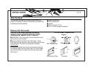
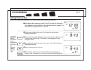
■ After labeling wires, disconnect them from
the existing thermostat terminals.
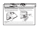
■ Remove existing wallplate. To make sure
wires do not fall back into wall opening,
you may want to tape them to the wall.
■ If hole in wall is larger than necessary for wires, seal this hole so
that no hot or cold air can enter the back of the thermostat from
the wall. This air could cause a false thermostat reading.
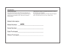
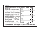
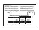
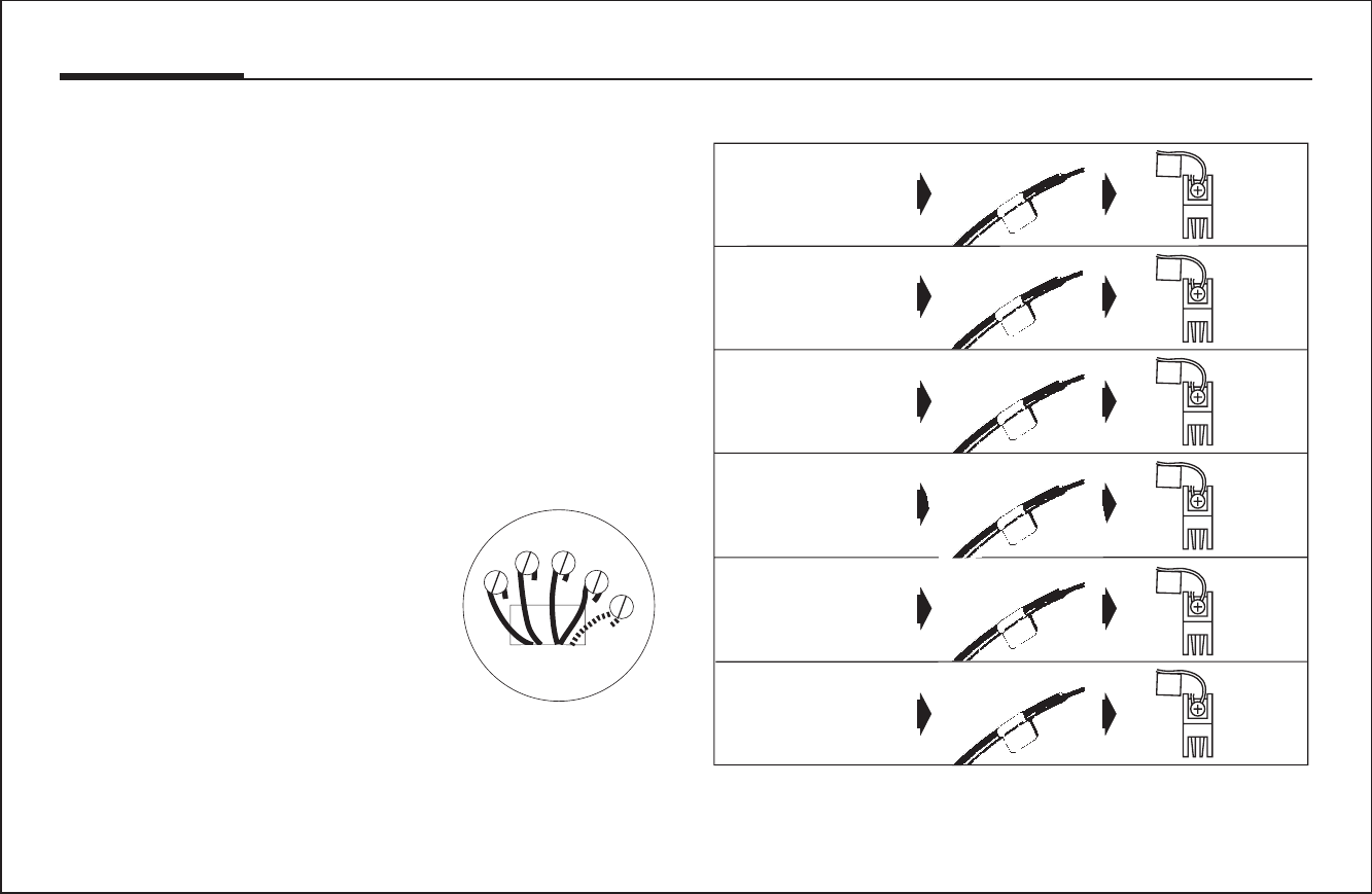
Wire Labeling
If the code letter on your
existing thermostat is
then mark the wire
with label shown
and connect to thermostat
terminal shown
NOTE: Do not connect a “Common” wire (sometimes labeled “C”) to any terminal on this thermostat. Tape up the wire and
do not use. This wire provides electricity to non-battery powered thermostats.
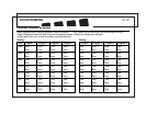
W
G
Y
RH
RC
RH
G
W
RC
O/B
Y/Y1
RH
RH
RC
RC
G
G
Y/Y1
Y/ Y1
W
W
O/B
O/B
RH, R,
VR or 4
24 Volt
G or F
Fan
RC, VC
24 Volt Cool
Y, Y1, C or M (See Note)
Air Conditioning
Compressor
W or H
Heating
Not for heat pumps
O, B, or R
Reversing Valve
(Single-stage
Heat Pumps only)
Table A