


4
®
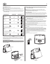
Wiring Diagrams
Fan Option
(SW6)
System Selector
(SW5)
STD HP
DISABLE ENABLE
Auto Recovery
(SW4)
HG HE
X - No Connection
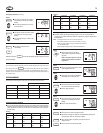
4-wire Heat/Cool System
Jumper
Wallplate
Terminals
Fan
Relay
Cool
Contactor
Heat Relay
or Valve
24V Supply
Heat/Cool
Rh
Rc
Y/O
W/B
Y1
G
X
X
System
Selector
STD
HP
–
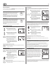
No Jumper
Wallplate
Terminals
Fan
Relay
Cool 24V
Supply
Heat Relay
or Valve
Heat 24V
Supply
Rh
Rc
Y/O
W/B
Y1
G
Cool
Contactor
X
System
Selector
STD
HP
–
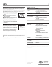
Jumper
X
OR
Heat
Mode
Cool
Mode
Connect to Proper Reversing
Valve Terminal. See Table A
System
Selector
STD
HP
–
Wallplate
Terminals
Rh
Y/O
W/B
Rc
G
Fan
Relay
Reversing
Valve
Compressor
Contactor
Y1
Heat Pump
24V Supply
5-wire Heat/Cool System
Single-stage Heat Pump System
Jumper
X
X
X
Wallplate
Terminals
Rh
Rc
Heat 24V or
Millivolt Supply
Heat Relay
or Valve
X
Y/O
W/B
Y1
G
System
Selector
STD
HP
–
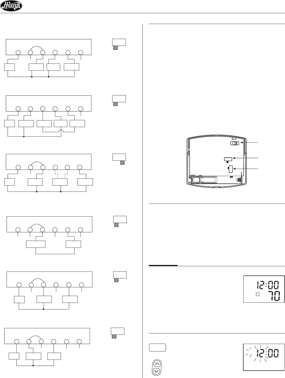
3-wire Heat Only System
Jumper
X
X
Wallplate
Terminals
Fan
Relay
Rh
Rc
Y/O
W/B
Y1
G
Heat 24V
Supply
X
Heat Relay
or Valve
System
Selector
STD
HP
–
2-wire Heat Only System
Rh
Rc
Y/O
W/B
Y1
G
Jumper
X
X
Wallplate
Terminals
Cool
Contactor
Cool 24V
Supply
Fan
Relay
X
System
Selector
STD
HP
–
3-wire Cool Only System
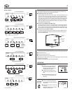
Selector Switches
In order for this thermostat to control your system, the system type must be specified by the
selector switches on the printed circuit board inside the thermostat.
■ Heating System Selector (HG - HE switch)
The factory position for this switch is in the “HG” position. Leave it in this position if you have
a gas furnace or an oil burner. If you have an electric furnace, test to see whether the Heat
and Fan come on as expected after installation. If the Fan operation is normal, leave it in the
“HG” position. If the Fan does not come on within a minute of the thermostat calling for heat,
change the switch position to “HE”. The system selector has no effect in the cooling mode.
NOTE: “HG” position is for gas and most other systems. “HE” position is for certain
electric systems having a fan relay.
■ System Selector (STANDARD - HEAT PUMP switch)
The factory position for this switch is in the STD position. Leave it in this position if you have
ANY system that uses gas, oil, electric, or hot water heating. If you have a single-stage Heat
Pump (no auxiliary or emergency heat source), then slide the switch to the HP position. Be sure
the reversing valve wire is connected to the correct terminal for your heat pump (Y/O) or (W/B).
■ Auto Recovery selector (DISABLE / ENABLE)
Your thermostat is set from the factory with the Auto Recovery Feature enabled, which com-
plies with the EPA ENERGY STAR
®
Program. If you prefer to use normal recovery, slide the
switch to the DISABLE position.
Figure 7
F˚ / C˚ Selection (Fahrenheit / Celcius)
Your thermostat is set for F˚ mode from the factory. To change to C˚ mode, follow these steps:
■ Press and hold the Up key.
■ Use a paper clip to press the reset key.
■ Once all the LCD segments turn on, release the Up key.
NOTE: To return to F˚ mode, press the reset key with a paper clip. Do not press any other
keys during the reset process.
All programs and settings will be lost when pressing RESET.
OPERATION
Setting Day and Time
■ The LCD will show this information when
batteries are first installed, or after the
Reset button is pressed. The temperature
will update after a few seconds.
■ During time and day setting mode, the
temperature and program displays will go
blank.
■ Example: Set the Thermostat to the current
time of 2:16 pm on Saturday. Refer to the
Steps below.
STEP 1:
■ Press to enter time and day setting mode.
The current hour and the AM / PM indicator
will be flashing.
■ Press to change the Hour up or down to the
current hour.
Note the AM / PM indicator, as the display
will change at 12 AM and 12 PM.
(Continued)
M
AM
4
TEMP
M
AM
day/time