


6
43553-01 • 05/15/09 • Hunter Fan Company
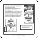
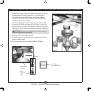
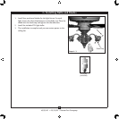
1. Uninstall the two attachment screws from the switch housing cover.
2. Remove the plug or screw from the center of the switch housing cover.
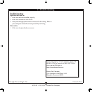
3. read the switch housing cover onto the light xture. Align the screw
holes in the light xture with the screw holes in the switch housing cover.
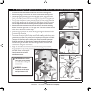
4. Use the two attachment screws removed from the lower switch housing
and the lock washers on the red tag of the light xture. Install the screws
into the light xture and the housing. Securely tighten the two screws.
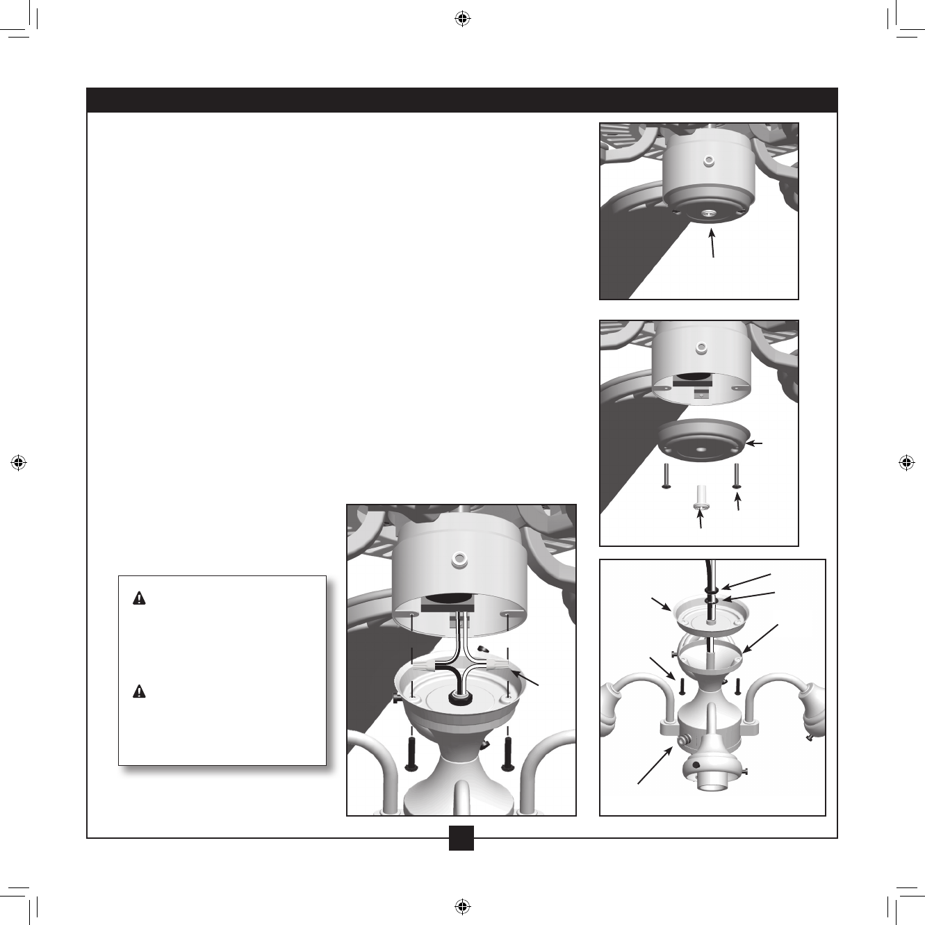
5. Remove the wire connectors from the two wires in the switch housing
labeled “Connect Light Here” or “For Light Use.” One wire is white and the
other wire is black with a white stripe.
6. Feed the two wires from the switch housing through the threaded rod in
the upper light housing.
7. To connect the wires, hold the bare metal leads together and place a wire
connector over them, then twist the wire connector clockwise until tight.
Connect the black wire with a white stripe from the switch housing to
the black wire from the light xture. Connect the white wire from the
switch housing to the white wire from the light xture. Secure all wire
connections using wire connectors.
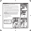
8. Align the threaded screw holes in the switch housing cover with the
threaded holes in the switch housing. Attach the switch housing cover
and light xture to the switch
housing using the included
attachment screws.
Switch
Housing
Cover
Plug
Nut
Washer
Screw
Hole
Switch
Housing
Cover
Attachment
Screw
Light Fixture
Non-Removable Switch
Housing
Steps 1-2
Steps 3-6
Attachment
Screw
Wires
and Wire
connectors
Step 7
CAUTION: Be sure no bare
metal wires or wire strands
are visible after making the
connections.
WARNING: Improper
installation could cause
the light xture to fall.
2 • Installing the Light fixture on Fans With Non-Removable Switch Housings