


41643-01 07/11/2003
STEP 2: Wiring the Fixture - Ceiling Light
NOTE: Refer to Figures 2 and 3 for the steps below.
1. Locate the green ground wire from the light
fixture and the supply ground wire coming out of the
electrical box.
2. Connect both ground wires underneath the green
ground screw on the hanger bracket.
3. Using approved wire connectors:
* Connect the white wire from the light fixture to the
white supply wire coming out of the ceiling; and
* Connect the black wire from the light fixture to the
black supply wire coming out of the ceiling.
4. Spread the electrical splices so that the black
wires are on one side of the outlet box and the white
wires are on the other side.
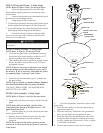
4. Leave the breakaway connector in place on the
upper chain.
5. Place the glass globe over the pipe nipple and up
against the upper cap.
6. Place the lower cap, without the side grommetted
hole, over the nipple and up against the glass.
7. Place the finial over the threaded pipe and, while
letting the chain and plastic connector retract into
the pipe, tighten the finial securely. Refer to Figure
4 for further clarification.
8. Turn the power back on at the electrical panel.
CAUTION
Be sure no bare wire or wire strands are visible after making
connections.
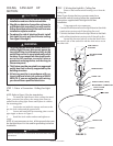
STEP 3: Fixture Assembly - Ceiling Light
NOTE: Refer to Figure 3 for the steps below.
1. Assemble the light fixture to the hanger bracket by
placing the holes in the canopy over the two 8-32”
screws protruding from the hanger bracket.
2. While holding the canopy against the ceiling, install
the two decorative nuts over the two 8-32”screws
and tighten securely.
NOTE: It may be necessary to adjust the screw length
from the hanger bracket by turning the screws out of
the bracket. If this is necessary, reassemble the fixture
by completing Step 3 sub-steps 1 and 2 above.
3. Install two 60 watt maximum type A-19 bulbs into
the lamp sockets.
NOTE: Type A-19 bulbs are Standard Shape, Standard
Size Household Medium Base Incandescent Bulbs.
CAUTION - RISK OF FIRE, USE MAXIMUM 60
WATT TYPE A-19 LAMPS.
STEP 4: Final Assembly - Ceiling Light
NOTE: Refer to Figures 3 and 4 for the steps below.
1. Temporarily turn the power back on at the electrical
panel.
NOTE: If the bulbs do not light, pull the chain,
coming out of the bottom of the light kit, once. The
lights should now be on.
2. With the lights on, go to the electrical panel and
turn the power back off.
3. Remove the lower chain extension from the light
fixture by unhooking it from the breakaway
connector.
NOTE: Do not discard the chain extension you just
removed as it will be needed if the fixture is converted
in the future.
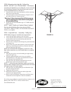
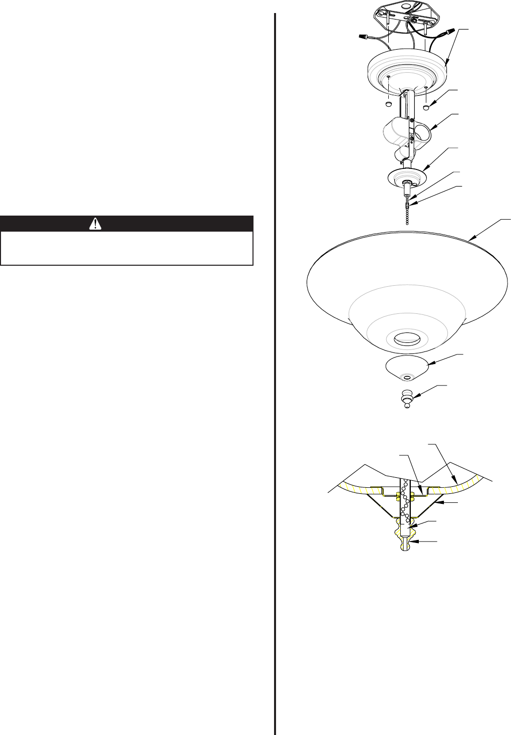
FIGURE 3
CANOPY
DECORATIVE
NUTS
LAMPHOLDER
UPPER CAP
UPPER LIGHT PULL
CHAIN
BREAKAWAY
CONNECTOR
GLOBE
BOTTOM CAP
FINIAL
FIGURE 4
BREAKAWAY
CONNECTOR
FINIAL
BOTTOM CAP
GLOBE
UPPER CAP