


®
Wiring Device-Kellems
Hubbell Incorporated (Delaware)
185 Plains Road
Milford, CT 06461-2420
(203) 882-4800
H-MOSS
®
Motion Switching System
Passive Infrared / Ultrasonic Occupancy Sensors
Installation and Operating Instructions
DESCRIPTION
The H-MOSS® sensor is an intelligent self-adapting occupancy
sensor that is designed to replace existing wall switches.
SPECIFICATIONS
• 1000 sq. ft coverage area (Models: AP1277 and AD1277)
• 400 sq. ft. coverage area (Models: AU1277)
• Single or Dual circuit 120/277VAC, 50/60Hz operation
• Electrical Ratings: (Each Output Separately) 120VAC – 800W
Incandescent, 1000W Ballast, 1/6 HP 277VAC – 1800W Ballast,
1/6 HP
• Adjustable Time Delay: 4-30 minutes, self-adapts based on
occupancy
• Light Level Adjustment (Circuit B output on Dual Circuit versions):
10-500+FC
• UL Listed
PRECAUTIONS
CAUTION: RISK OF ELECTRICAL SHOCK. Turn power off at
service panel before beginning installation. Never wire energized
electrical components.
Read and understand all instructions before beginning installation.
NOTICE: For installation by a licensed electrician in accordance with
National and/or local Electrical Codes and the following instructions.
NOTICE: For indoor use only.
CAUTION: USE COPPER CONDUCTOR ONLY.
Confi rm that device ratings are suitable for the application prior to
installation.
NOTICE: Do not install if any damage to product is noticed.
INSTALLATION
1. Turn power off at the service panel.
2. Remove the old switch(es) if applicable.
3. Wire as shown in the Wiring Diagram section. A secure connection
to ground is necessary for the sensor to function properly.
4. Install sensor in wall box using mounting screws provided.
5. Restore power to the sensor and allow it to self adjust (up to 2min.).
6. Remove the sensor’s cover – see Adjustments section.
7. If desired, calibrate the photocell sensor and adjust the sensor’s
confi guration switch settings as described below.
8. Reinstall the sensor’s cover.
9. Install a Style Line® wall plate (not included).
Test Mode – to enter test mode:
1. Make sure lights are on.
2. Press and hold the ON/OFF button until the lights cycle off then
back on. For dual circuit sensors, press and hold the ON/OFF
button for Circuit A. For No-button sensors, press and hold the
Test Button. See Sensor Operation Diagram.
3. Sensor is now in test mode. Vacate room, lights should turn off
after 5 seconds. Step back into room (sensing zone), lights will
turn back on. Repeat as necessary to confi rm sensor is operating
and detecting in the lighting zone as desired. Sensor will fl ash red
or green LED to indicate Passive Infrared or Ultrasonic occupancy
detection as applicable.
4. To exit Tes t Mode, press any button. Note: Sensor will automatically
exit Test Mode after 1 hour.
Manual Override – Press button(s) to toggle lights ON and OFF.
Lights will remain in the last state determined by the buttons while
occupancy is detected. Sensor will return to automatic mode when
the sensor’s unoccupied timer value is reached. Note: No-button
sensors cannot be manually turned off.
PD2218 Page 1 04/09 PRINTED IN USA
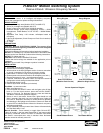
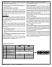
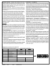
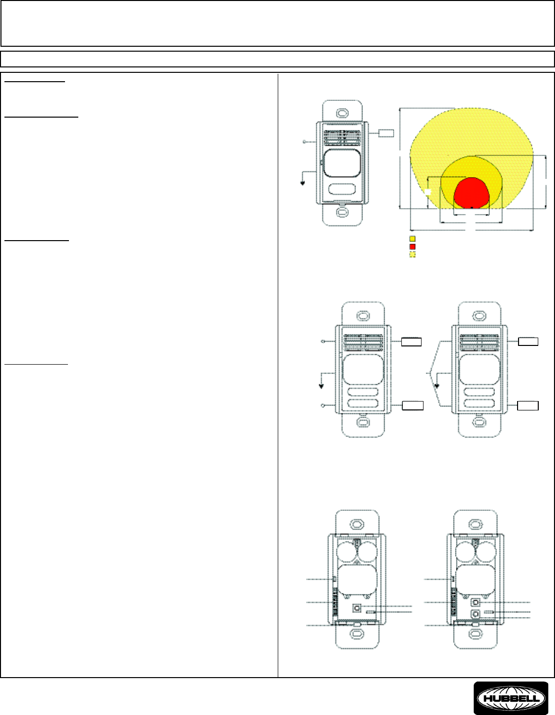
Wiring Diagram
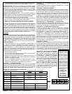
Range Diagram
120/277VAC
Black
Green
Ground
Red
Load 1
Single Circuit
US Major motion
US Minor motion
PIR Major Motion
50 '
26 '
16 '
29 '
56 '
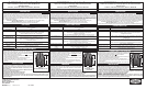
Sensor Operation Diagram
One/No Button Sensor Two Button Sensor
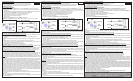
Photocell
Push-Button
Confi guration
Switches
Cover Release
Catch
Button A
(Test Button)
Air Gap Switch
Photocell
Push-Button
Confi g-
uration
Switches
Cover Release
Catch
Button A
(Test Button)
Air Gap Switch
Button B
15 '
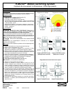
Line circuit 1
120/277 VAC
Black
Green
Ground
Dual Circuit Sensor
(Wired for Dual Circuits)
Blue
Line circuit 2
120/277 VAC
Red
Load 1
Load 2
Violet
Line circuit
120/277 VAC
Dual Circuit Sensor
(Wired for Single Circuit)
Black
Green
Ground
Blue
Red
Load 1
Load 2
Violet
Load 2
Load1
Load 2
Load1