


HUAWEI EM820W HSPA+ PC Embedded Module
Hardware Guide Description of the Application Interfaces
Issue 01 (2010-12-31)
Huawei Proprietary and Confidential
Copyright © Huawei Technologies Co., Ltd.
12
module board before entering the EM820W processor. There is also an EMI filtering
and ESD protection circuit between the SIM card interface and the Mini PCI interface
on the user’s board.
z
Power supply
The SIM card interface is powered by an internal LDO regulator of EM820W.
The default value of this regulator is 2.85 V. The power of the regulator is
programmable in the range of 1.5 V to 3.05 V and is expected to be set to 3.0 V
or 1.8 V.
z
Modem signals
After a power-on or reset, the USIM signals are activated to detect if a SIM card
is present and to initialize it if it exists. Once a SIM card has been detected and
initialized, the interface is always on. However, the clock signal is only activated
when data is actually being transmitted. The USIM signals from the module are
connected to the level translators, and then to the Mini Card host connector.
− The UIM_DETECT pin is optional, depending on whether this function is
required.
− For UIM_DATA, it does not need to add a pull-up resistor, because it has
been pulled up to UIM_PWR with a 15 kΩ resistor on the module, in
compliance with the ISO/IEC 7816-3.
− For UIM_PWR, it is recommended to add an additional decoupling capacitor
ranging from 1uF to 10uF, and to place a 10pF capacitor on each of the
signals such as UIM_RST, UIM_CLK and UIM_DATA.
These levels exceed those required in ISO/IEC 7816-3.
z
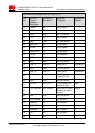
SIM signals
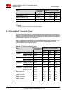
The following data is taken from the ETSI standard Specification of the 3 Volt
Subscriber Identity Module - Mobile Equipment (SIM-ME) interface (GSM 11.12
version 4.3.1).
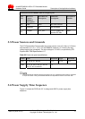
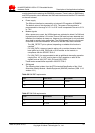
Table 3-6 SIM RST requirements
RST Minimum Maximum
V
IL
0 0.2Vcc
V
IH
0.7Vcc Vcc
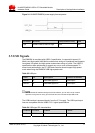
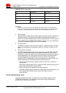
Table 3-7 SIM CLK requirements
CLK Minimum Maximum
V
IL
0 0.2Vcc
V
IH
0.7Vcc Vcc