


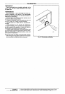

2. Firmly tighten each terminal screw.
3. Fit wires as close to the subbase as possible. Push
excess wire back into hole.
4. Plug hole with nonflammable insulation to prevent
drafts from affecting the thermostat.
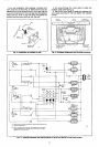
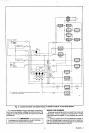
Fig. 6-Wiring conneciions.
MOUNTING THE THERMOSTAT
1. Remove the thermostat cover by pulling the bottom
edge of the cover upward until it snaps free of the
retaining posts.
NOTE: The covar is hinged at the top and must be
removed by pulling up at the bonom.
2. Carefully remove and discard the polystyrene
packing insert which protects the mercury switches
during shipment.
3. Turn the thermostat base over and note the spring
fingers which engage the subbase contacts. Make sure
the spring fingers are NOT bent flat, preventing proper
electrical contact with the subbase.
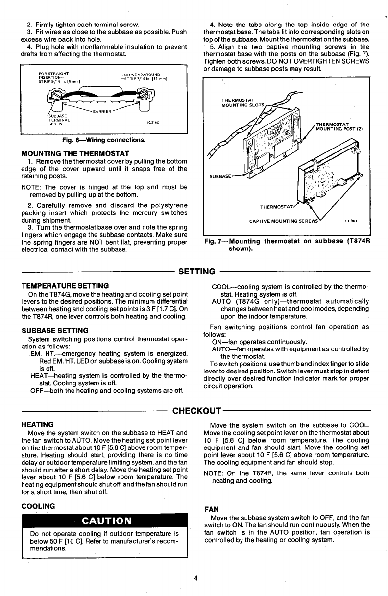
4. Note the tabs along the top inside edge of the
thermostat base. The tabs fit into corresponding slots on
top of the subbase. Mount the thermostat on the subbase.
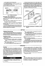
5. Align the two captive mounting screws in the
thermostat base with the oosts on the subbase fFia. 7).
Tighten both screws. DO NOT OVERTIGHTEN SCREWS
or damage to subbase posts may result.
t
:ig. 7-Mounling thermostat on subbase (T874R
shown).
SETTING
TEMPERATURE SETTING
COOL-cooling system is controlled by the thermo-
On the T874G, move the heating and cooling set point stat. Heating system is off.
levers to the desired positions. The minimum differential AUTO (T874G only)-thermostat automatically
between heating and cooling set points is 3 F [1.7 C]. On changes between heat and cool modes, depending
the T874R one lever controls both heating and cooling. upon the indoor temperature.
SUBBASE SETTING
System switching positions control thermostat oper-
ation as follows:
EM. HT.-emergency heating system is energized.
Red EM. HT. LED on subbase is on. Cooling system
is off.
HEAT-heating system is controlled by the thermo-
stat. Cooling system is off.
OFF-both the heating and cooling systems are off.
Fan switching positions control fan operation as
follows:
ON-fan operates continuously.
AUTO-fan operates with equipment as controlled by
the thermostat.
To switch positions, usethumband indexfingertoslide
lever to desired position. Switch lever must stop in detent
directly over desired function indicator mark for proper
circuit operation.
CHECKOUT
HEATING
Move the system switch on the subbase to HEAT and
the fan switch to AUTO. Move the heating set point lever
on the thermostat about 10 F [56 C] above room temper-
ature. Heating should start, providing there is no time
delay or outdoortemperature limiting system, and the fan
should run after a short delay. Move the heating set point
lever about 10 F [56 C] below room temperature. The
heating equipmentshould shutoff, and the fan should run
for a short time, then shut off.
Move the system switch on the subbase to COOL.
Move the cooling set point lever on the thermostat about
10 F [56 C] below room temperature. The cooling
equipment and fan should start. Move the cooling set
point lever about 10 F [5.6 C] above room temperature.
The cooling equipment and fan should stop.
NOTE: On the T874R, the same lever controls both
heating and cooling.
COOLING
below 50 F [lo Cl. Refer to manufacturer’s recom-
Move the subbase system switch to OFF, and the fan
switch to ON. The fan should run continuously. When the
is in the AUTO position, fan operation is
controlled by the heating or cooling system.
4