.
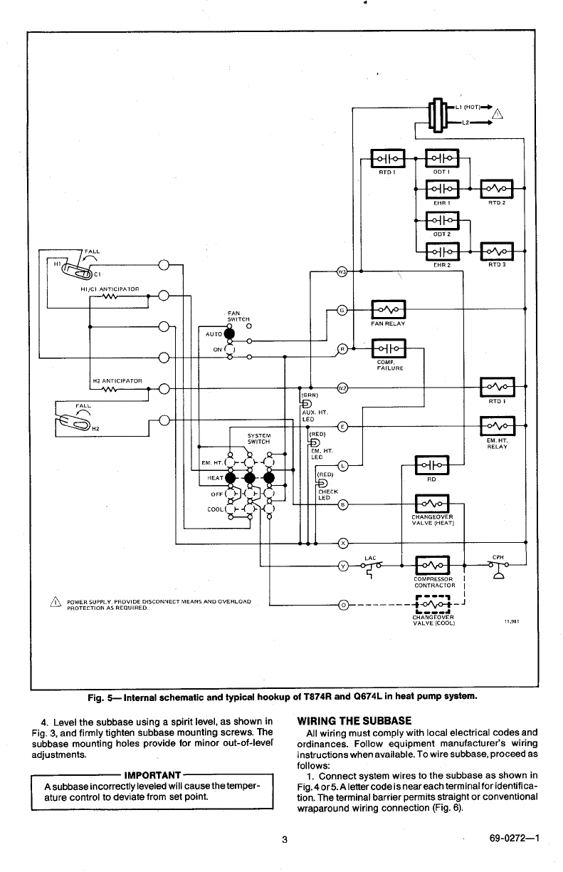
Fig. 5-Internal schematic and typical hookup of T8?4R and Q674L in heat pump system.
4. Level the subbase using a spirit level, as shown in
Fig. 3, and firmly tighten subbase mounting screws. The
subbase mounting holes provide for minor out-of-lever
adjustments.
ature control to deviate from set point.
3
6g-0272-1
WIRING THE SUBBASE
All wiring must comply with local electrical codes and
ordinances. Follow equipment manufacturer’s wiring
instructions when available. To wire subbase, proceed as
follows:
1. Connect system wires to the subbase as shown in
Fig.4orSAlettercode is neareach terminal for identifica-
tion. The terminal barrier permits straight or conventional
wraparound wiring connection (Fig. 6).


