INSTALLATION INSTRUCTIONS FOR THE TRAINED SERVICE TECHNICIAN
APPLICATION
Thesethermostats and subbases provide 24 to 30 Vat control for two-stage heating and one-stage cooling heat pump
systems as follows:
MODEL I CHANGEOVER 1 SYSTEM SWITCHING 1 FAN SWITCHING
Y594G (T874GIQ674F)
Automatic (Heat or Cool)
OFF-EM.HT.-HEAT-
AUTO-ON
AUTO-COOL
T874RlQ674L
Manual 1 EM.HT.-HEAT-OFF-COOL 1 AUTO-ON
OPERATION
On a two-heat thermostat, the two stages of heat
“make” sequentially as the temperature drops. “Make”
refers to the mercury switch initiating a call for heat or
COOL
There is about 2 F [1 .I C] between stages so that the
second stage (auxiliary heat) makes only when the first
stage can’t handle the load. This is the interstage
differential.
Three LEDs (light-emitting diodes) are included on the
subbase. The red CHECK LED lights when something
needs to be checked or done to maintain efficient
operation of the system. See your heating system
instructions to find out specifically what the CHECK LED
signifies. The green LED lights when the AUX. HT. stage
(second stage) heat is operating. The red EM.HT. LED
lights when the EM.HT. relay is energized, usually
operating electric strip heaters.
INSTALLATION
WHEN INSTALLING THIS PRODUCT. . .
1. Read these instructions carefully. Failure to follow
them could damage the product or cause a hazardous
condition.
2. Check the ratings given in the instructions and on
the product to make sure the product is suitable for your
application.
3. Installer must be a trained, experienced service
technician.
4. After installation is complete, check out product
operation as provided in these instructions.
1. Disconnect power supply to prevent electrical
shock or equipment damage.
2. Run wires as close to the subbase as possible.
To prevent interference with the thermostat
linkage, keep wire length to a minimum. Push
excess wire back into the hole, and plug hole to
prevent drafts from affecting thermostat
operation.
3. Do not overtighten thermostat captive mounting
screws as damage to subbase threads may
result.
4. Do not short across coil terminals on relay. This
may burn out the heat anticipator.
LOCATION
Install thethermostatabout5ft]l.5 m]abovethefloor in
an area with good circulation at average temperature.
Do not install the thermostat where it may be
affected by-
-drafts, or dead spots behind doors and in
corners.
-hot or cold air from ducts.
-radiant heat from sun or appliances.
-concealed pipes and chimneys.
-unheated (uncooled) areas behind the ther-
mostat, such as an outside wall.
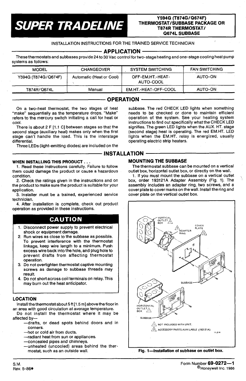
MOUNTING THE SUBBASE
The thermostat subbase can be mounted on a vertical
outlet box, horizontal outlet box, or directly on the wall.
1. If you must mount the subbase on a vertical outlet
,
box, order 19312lA Adapter Assembly (Fig. 1). The
assembly includes an adapter ring, two screws, and a
cover plate to cover marks on the wall. Install the ring and
cover plate on the vertical outlet box
Fig. l-Installation of subbase on outlet box.
SM.
Rev. 5-86.
Form Number 69-0272-1
@Ho”eyweli Inc. 1986


