69-0920
8
Y594 (MULTISTAGE THERMOSTAT SUBBASE) PACKAGE
Home and Building Control
Honeywell International, Inc.
1985 Douglas Drive North
Golden Valley, MN 55422
1.2
.4
.6
.3
.2
.15
.12
.1
0
.8
MOVE INDICATOR TO
MATCH CURRENT RATING
OF PRIMARY CONTROL
STAGE TWO
ANTICIPATOR
HEATING CONTROL
M4550
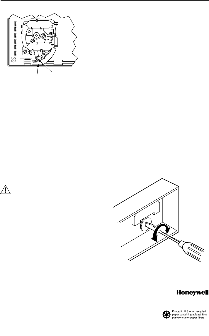
Fig. 8. Adjustable heat anticipator shown.
To switch positions, use thumb and index finger to slide
lever to desired position. Switch lever must stop in detent
directly over the desired function indicator mark for proper
system operation.
CHECKOUT
Heating
Set the system switch on the subbase at HEAT or ON and
the fan switch at AUTO. Move the heating lever on the
thermostat about 10°F (6°C) above room temperature.
Heating (both stages if two-stage thermostat) should start
if there is no time delay or outdoor temperature limiting
system, and the fan should come on. Move the heating
lever about 10°F (6°C) below room temperature. Heating
and fan should shut off.
Cooling
CAUTION
Do not operate cooling if outdoor temperature is
below 50°F (10°C). Refer to manufacturer recom-
mendations.
Set the system switch on the subbase to COOL or ON and
the fan switch to AUTO. Move the cooling lever on the
thermostat about 10°F (6°C) below room temperature.
Cooling and fan should start. Move the cooling lever about
10°F (6°C) above room temperature. Cooling and fan
should stop.
Fan
Set the fan switch to ON. Move the system switch to
different positions; the fan should run continuously. Move
the fan switch to AUTO. Move the system switch to
different positions. Fan operation is controlled with the
heating or cooling system.
LED Indication
Set system switch on subbase at SUPL. HT. The SUPL.
HT. LED should light. Simulate compressor failure and
energize the system. The FAULT LED should light.
CALIBRATION
Thermostat
These thermostats are accurately calibrated at the factory.
They do not
have provision for field calibration
.
Thermometer
The thermometer in your thermostat has been accurately
calibrated at the factory. The thermometer should only
adjustment if it has been dropped or shifted due to
mishandling.
If the setpoint lever and the thermometer reading do not
agree, use the following procedure:
ᕡ Remove the thermostat cover by pulling up from the
bottom edge of the cover away from the base until it
snaps free of the cover clip.
ᕢ Set the thermostat cover on a table near an
accurate thermometer.
ᕣ Allow ten minutes for cover thermometer to sense
area temperature; compare the readings. Be careful
not the touch the thermometer or breathe on it.
ᕤ If the readings are the same, replace cover and put
the system into operation.
ᕥ If the readings are different, insert a small screw-
driver in the thermometer slot and turn it until the
thermometers have the same reading. See Fig. 9.
ᕦ Replace thermostat cover and put the system into
operation.
M5070
Home and Building Control
Honeywell Limited-Honeywell Limitée
35 Dynamic Drive
Scarborough, Ontario
M1V 4Z9
J.H. 5-95 www.honeywell.com/yourhome
Fig. 9. Thermometer calibration.


