


69-0920
3
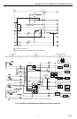
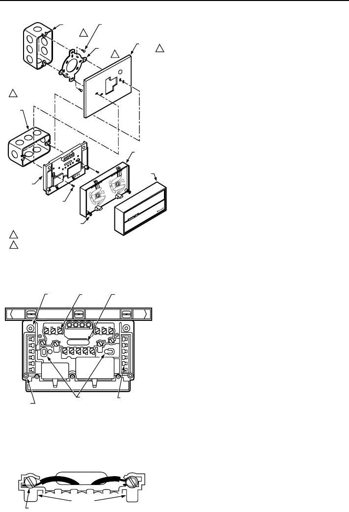
Y594 (MULTISTAGE THERMOSTAT SUBBASE) PACKAGE
M6009
VERTICAL
OUTLET
BOX
ADAPTER
RING
COVER
PLATE
MOUNTING
SCREWS (2)
1
SUBBASE
SUBBASE
MOUNTING SCREWS (2)
HORIZONTAL
OUTLET
BOX
1
2
2
1 NOT INCLUDED WITH UNIT.
2 ACCESSORY PARTS AVAILABLE (193121A).
THERMOSTAT
CAPTIVE
MOUNTING SCREWS (2)
5
0 6
0
7
0
8
0
5
0
6
0
7
0
8
0
H
E
A
T
C
O
O
L
THERMOSTAT
COVER
50 60 70 80
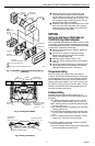
Fig. 1. Installation of subbases and thermostat on
outlet box.
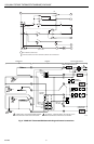
SPIRIT LEVEL
MOUNTING
HOLES (2)
M927
TOP
MOUNTING
HOLES (2)
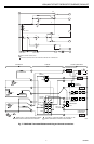
WIRING
TERMINAL
THERMOSTAT
CABLE OPENING
TO SPRING FINGER
CONTACTS ON THE
THERMOSTAT
(UP TO 12)
POST (2) FOR
MOUNTING
THERMOSTAT
Fig. 2. Leveling the subbase.
Fig. 3. Wiring connections.
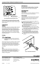
FOR STRAIGHT
INSERTION–
STRIP 5/16 in. (8 mm)
FOR WRAPAROUND–
STRIP 7/16 in. (11 mm)
SUBBASE TERMINAL SCREW
M928
BARRIER
ᕥ Note the tabs along the top inside edge of the
thermostat base. The tabs fit into the subbase
notches. Mount the thermostat on the subbase and
tighten the captive mounting screws. See Fig. 1. Do
not overtighten captive mounting screws. This can
damage the threads in the subbase.
ᕦ Place the upper edge of the thermostat cover on the
base and swing cover downward until it engages
retaining posts on base. Tighten the locking cover
screws if assembly is provided.
SETTING
Setting the 2nd Stage (Y594G1666 and
Y594G1674 Only) Heat Anticipator
Set the adjustable heat anticipator to match its primary control
current draw. If the primary control nameplate has no rating or
if further adjustment is necessary, use the following procedure
to measure the current draw of each stage:
ᕡ Remove thermostat from the subbase. Make sure
the power is on.
ᕢ Connect an ac ammeter of appropriate range
between the heating terminals of the subbase:
Stage 2: between W2 and R.
ᕣ Move the system switch to HEAT or ON.
ᕤ After one minute, read the ammeter and record the
reading.
ᕥ Remount the thermostat and use a ballpoint pen to
set the adjustable heat anticipator(s) to match the
reading(s) measured in step 4. See Fig. 8.
Temperature Setting
Move the heating and cooling levers to the desired
positions. The minimum differential between heating and
cooling setpoints is 3°F (2°C). Some thermostat models
have nonadjustable lever stops, which set the maximum
heating control point at 68°F or 72°F (20°C or 22°C) and
the minimum cooling control point at 78°F (26°C). Do not
attempt to exceed these limits. Some models have only
one lever for heating and cooling.
Subbase Setting
Available subbase system switch positions vary by
thermostat model. Positions control thermostat operation
as follows:
OFF: Heating and cooling systems are off. If the fan
switch is at the AUTO position, the fan is also off.
HEAT: Heating system is controlled by the thermostat.
Cooling system is off.
COOL: Cooling system is controlled by the thermostat.
Heating system is off.
ON: Thermostat automatically switches between heat
and cool modes, depending on the indoor tempera-
ture.
SUPL. HT.: Supplemental heat is energized. Cooling
system is off. Compressor cannot operate.
Fan switching positions control fan operation as follows:
ON: Fan operates continuously.
AUTO: Fan operates with heat pump and supplemental
heat as controlled by the thermostat.