


X-XX UL
INSTALLATION INSTRUCTIONS
Copyright © 1995 Honeywell Inc. • • All Rights Reserved
APPLICATION
These Y594G and Y594J combination packs are designed
to meet the specific requirements of Carrier heat pump
equipment. The Y594 packs are designed for 2 stage heat
and 1 stage cool applications. The system switch is SUPL
HT-HEAT-OFF-COOL or SUPL HT-ON-OFF. The fan
switch is AUTO-ON. See Table 1 for model information
and cross reference from Carrier part numbers.
69-0920
TRADELINE
®
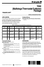
Y594
(Multistage Thermostat Subbase)
Package
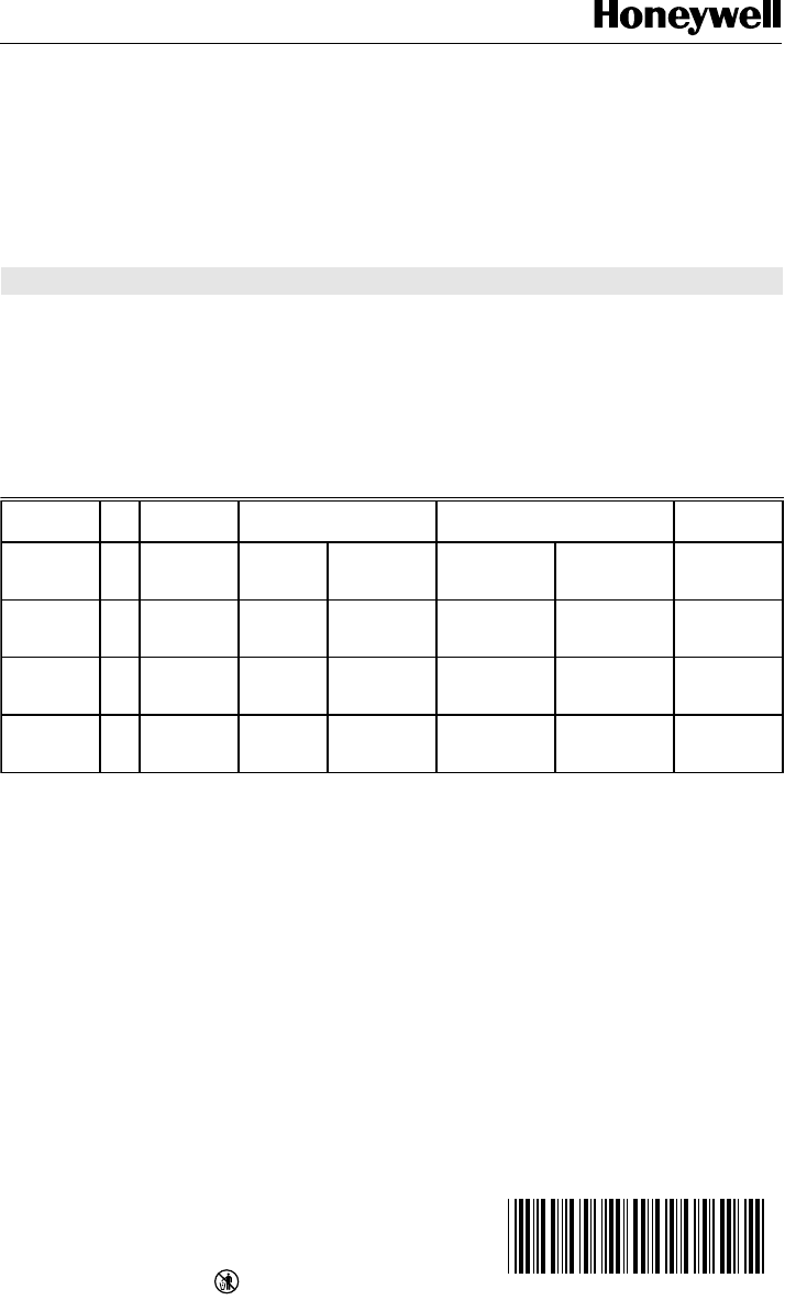
Table 1. Heat Pump Thermostat/Subbase Combinations.
OS No.
Fig.
No. Contains Replaces Honeywell Replaces Carrier
Changeover
Mode
Y594G1666 7 T874G2004
Q674L1892
Y507J1011 T874G1055
Q674L1041
99TZ90041106 HH07AT171
HH93AZ175
Manual
changeover in
cooling
Y594G1674 6 T874G2004
Q674J1274
Y507J1003 T874G1055
Q674J1035
99TZ90040106 HH07AT171
HH93AZ173
Auto
changeover in
cooling
Y594J1001 5 T874J1069
Q674L1900
— T874J1002
Q674L1074 or
Q674L1637
— HH07AT175
HH93AZ186 or
HH93AZ195
Manual
changeover in
cooling
Y594J1019 4 T874J1069
Q674J1282
— T874J1002
Q674J1068 or
Q674J1159
— HH07AT175
HH93AZ183 or
HH93AZ196
Auto
changeover in
heating
Thermostat Ratings
SWITCHING: sealed mercury switch.
SWITCH RATINGS:
First Stage Heating and Cooling: 6.5A inrush, 1.5A
maximum running at 25 Vac.
Second Stage Heating and Cooling: 1.5A maximum
running at 30 Vac.
Changeover Switch: 6.5A inrush, 1.5A running at 25
Vac.
HEAT ANTICIPATOR:
First Stage Heating and Cooling: fixed voltage type,
1.0A.
Second Stage Heating: adjustable, 0.10 to 1.2A; other
models, fixed voltage type, 1.0A.
TEMPERATURE SETTING RANGE: 42°F to 88°F (6°C to
31°C).
Subbase Ratings
SWITCH RATING: 7.5A inrush, 2.5A running at 30 Vac.
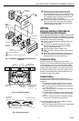
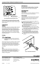
MOUNTING: Designed for mounting on wall or horizontal
outlet box.
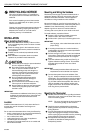
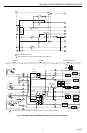
OPERATION
The two stages of heat are energized sequentially with
changes in temperature. Stage one comes on first; then if
the temperature at the thermostat continues to move away
from the setpoint, the second stage comes on. The
thermostat is set with about 2°F (1°C) between stages. As
the heating equipment runs and the temperature begins to
move back toward the set point, stage 2 goes off first, then
stage one.
Subbases include an LED (light emitting diode) indicator.
This indicator lights to show that the heat pump cannot
operate and the supplemental heat stage is providing all
heating. This condition can occur in two instances; when
the subbase system switch is set at SUPL. HT. and when
the heat pump compressor has malfunctioned.
The LEDs are not field replaceable.