


V4943/V8943B,C,N; V4944/V8944B,C,L,N REGULATING DIAPHRAGM GAS VALVES
9 65-0214—08
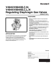
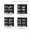
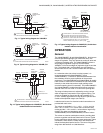
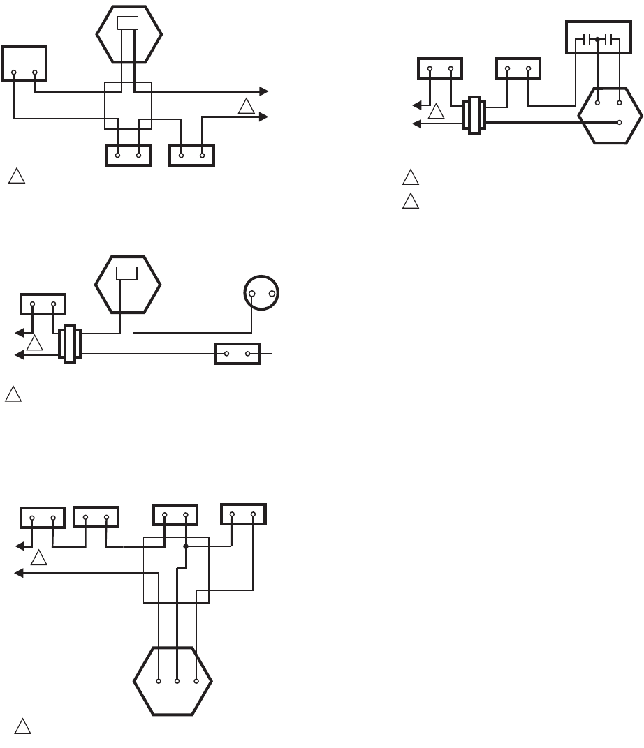
Fig. 11. Typical wiring diagram for V4943B,N.
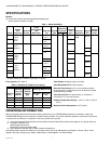
Fig. 12. Typical wiring diagram for V8943B,C,N.
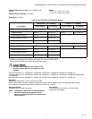
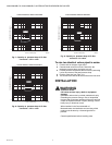
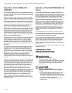
Fig. 13. Typical wiring diagram for V4944B,C,L,N with three
leadwire electrical termination.
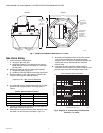
Fig. 14. Typical wiring diagram for V8944B,C,L,N with three
leadwire electrical termination.
OPERATION
General
The V4943/V8943B,C, N and V4944/V8944B,C,L, N Valves are
solenoid-operated diaphragm gas valves with one or two
stages of regulation. They can operate as a shut-off valve and
a pressure regulating valve. The V4943/V8943B,C,N have a
single stage of regulation (high fire) and the V4944/
V8944B,C,L,N have two stages of regulation (high fire and low
fire). The models with L and N suffixes are rapid opening
devices while the B- and C-suffixed models are slow opening
devices.
In a redundant valve (two valves in series) system, it is
recommended that the V4943/V8943B,C, N and
V4944/V8944B,C,L, N Valves be positioned downstream from
the redundant valve for proper operation of the pressure
regulator(s). The V4943/V8943N and V4944/V8944L,N models
have a 0.022 in. bleed orifice in the bleed line (the valves bleed
internally to the outlet side) and are rapid opening valves
(maximum opening time is six seconds). The V4943/V8943B,C
and V4944/V8944B,C models have bleed orifices varying in
diameter from 0.014 to 0.018 in. to control the opening time.
The range of outlet pressure is adjusted by turning a screw
which changes the compression in the regulator spring. The
valves are suitable for natural gas (B and N models) or LP
(C and L models) applications. Do not adjust or operate valve
outside of the specified ranges (see Table 3).
Leadwires and a cover for electrical conduit connections are
provided with each valve.
The valves are available in 1 in., 1-1/4 in., 1-1/2 in. and 2 in.
sizes. The 1 in. and 1-1/4 in. valves share a common body
casting and the 1-1/2 in. and 2 in. valves share a larger body
casting. The valves are intended to replace the
V4843/V8843B,C,N and V4844/V8844B,C,N lines of valves.
The valves are used as combination controls, providing both
pressure regulation and shutoff functions for burners. Typical
burner applications include boilers, process equipment, ovens,
incinerators, water heaters, rooftop units, and commercial/
industrial atmospheric/power burners. The burner firing rates
range from 400 kbtu/hour to 5,000 kbtu/hour.
L1
(HOT)
L2
1
LIMIT(S)
POWER SUPPLY. PROVIDE DISCONNECT MEANS
AND OVERLOAD PROTECTION AS REQUIRED.
M6887
FLAME
SAFEGUARD
CONTROL
1
JUNCTION
BOX
LINE VOLTAGE
THERMOSTAT
OR CONTROLLER
V4943B,C,N
SINGLE-STAGE
VALVE
PV
PV
MV
BLACK ORANGE
L1
(HOT)
L2
1
LIMIT(S)
TRANSFORMER
1
POWER SUPPLY. PROVIDE DISCONNECT MEANS
AND OVERLOAD PROTECTION AS REQUIRED.
M6888B
24-VOLT
THERMOSTAT
FLAME SAFEGUARD
CONTROL
V8943B,C,N
SINGLE-STAGE
VALVE
PV
PV
MV
ORANGE
BLACK
L1
(HOT)
L2
1
LIMIT(S)
FLAME
SAFEGUARD
CONTROL
SECOND
STAGE
CONTROLLER
1
POWER SUPPLY. PROVIDE DISCONNECT MEANS
AND OVERLOAD PROTECTION AS REQUIRED.
M6886B
COM
STG 1
STG 2
ORANGE
BLACK
BLUE
V4944B,C,L,N
TWO-STAGE VALVE
PV
PV
MV
MV
CONTROLLER
L1
HOT
L2
1
LIMIT(S)
FLAME
SAFEGUARD
CONTROL
PV MV
PV
MV
TWO-STAGE
CONTROLLER
TRANSFORMER
1
POWER SUPPLY. PROVIDE DISCONNECT MEANS
AND OVERLOAD PROTECTION AS REQUIRED.
2
V8944B1050, V8944B1068, V8944B1076,V8944B1084
V8944C1041, V8944C1058, AND V8944C1066 HAVE A
MOLEX® CONNECTOR WITH 72 IN. (1829 MM) LEAD
WIRES: ORANGE (MV), PINK (PV), GRAY (COM).
M6889A
V8944B,C, L, N
TWO-STAGE VALVE
ORANGE
BLACK
BLUE