


V4943/V8943B,C,N; V4944/V8944B,C,L,N REGULATING DIAPHRAGM GAS VALVES
Automation and Control Solutions
Honeywell International Inc.
1985 Douglas Drive North
Golden Valley, MN 55422
customer.honeywell.com
® U.S. Registered Trademark
© 2011 Honeywell International Inc.
65-0214—08 M.S. Rev. 09-11
Printed in United States
Troubleshooting
WARNING
Electrical Shock Hazard.
Can cause electrical shock or equipment damage.
Use utmost care during troubleshooting. Line voltage
is present right at the electrical terminations for the
V4943B,C,N and V4944B,C,L,N valves, and present in
all controller circuits for all V4943/V8943 and V4944/
V8944 valves.
IMPORTANT
Do not assume that the valve must be replaced until
all other sources of trouble have been eliminated.
1. If the valve will not open when the thermostat or
controller calls for heat:
a. Check that there is voltage at the proper electrical
terminations. Be careful—there should be line
voltage at the actuator of V4943 and V4944 valves.
b. If there is no voltage at the actuator, first make sure
line voltage power is connected to the master
switch, the master switch is closed and overload
protection (circuit breaker, fuse or similar device)
has not opened the power line.
c. For V8943A only: If line voltage power is correct,
check transformer output. Replace the transformer if
necessary.
d. If there is still no voltage at the actuator, make sure
all appropriate contacts in the thermostat or
controller, limits and flame safeguard control are
closed. If one or more is open, determine the
cause(s) and correct the condition(s) before
proceeding.
e. If there is proper voltage at the valve actuator but
the valve still does not open, first check that the gas
pressure at the valve is normal.
f. If the valve still does not open, replace the valve.
2. If the valve will not close when one or more of the
appropriate contacts in the thermostat or controller,
limit(s) or flame safeguard control is open:
a. Make sure that the gas flow is in the direction of the
arrow on the valve body.
b. Make sure the valve actuator is wired in the correct
circuit. Open the master switch to remove power
from the valve actuator. If the valve closes now, the
actuator may not be wired properly. Check and
correct the wiring, if necessary.
c. Look for a short in the electrical circuit.
SERVICE INFORMATION
WARNING
Electrical Shock Hazard
Can cause serious injury, death or equipment
damage.
1. Only qualified service technicians should attempt to
service or repair flame safeguard controls and
burner systems.
2. Line voltage is present in the electrical circuits to the
valve. Open the master switch before replacing the
valve.
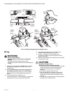
Scheduled Inspection and
Maintenance
For periodic inspection and maintenance, set up a schedule
and follow it. Include the burner valves (check for external
leakage around all seals and joints with leak detector; also
check for internal valve seat leakage—see Valve Leak Test
section) and all other controls. Refer to the flame safeguard
control instructions for more information.
CAUTION
Equipment Damage Hazard.
Can cause equipment damage or improper
operation.
Label all wires prior to disconnecting when servicing
valves. Wiring errors can cause improper and
dangerous operation.
Verify proper operation after servicing.