


V4943/V8943B,C,N; V4944/V8944B,C,L,N REGULATING DIAPHRAGM GAS VALVES
65-0214—08 6
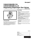
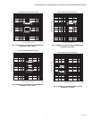
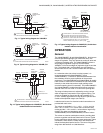
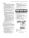
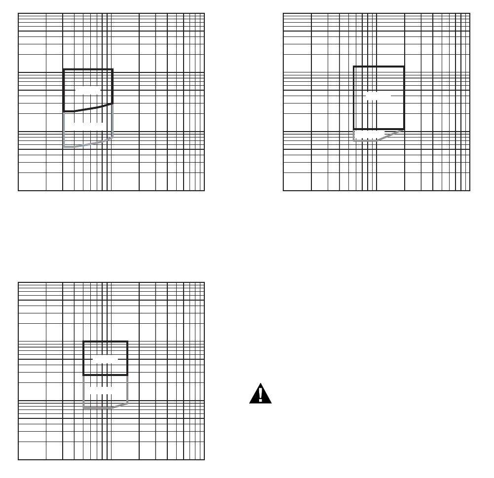
Fig. 7. Capacity vs. pressure drop of LP Gas
curves for 1-1/4 in. valve.
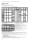
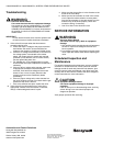
Fig. 8. Capacity vs. pressure drop of LP Gas
curves for 1-1/2 in. valve.
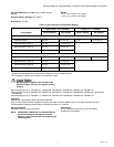
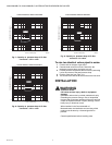
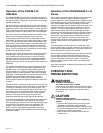
Fig. 9. Capacity vs. pressure drop of LP Gas
curves for 2 in. valve.
To size two identical valves piped in series:
1. Find the cf/h for the type of gas used.
2. Consider both valves as one unit. Determine the
maximum pressure drop across the one unit.
3. Find the pressure drop across the first valve by assuming
it to be 45 percent of the total pressure drop.
4. Find the valve size from Figs. 2–9.
5. The second valve will be the same size as the first valve.
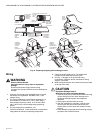
INSTALLATION
WARNING
Explosion hazard.
Can cause serious injury, death or equipment
damage.
Installation and service by trained professionals only.
Exceeding the pressure rating or use of unspecified
fuel can lead to improper operation of the valve and can
create an explosion hazard. Property damage, severe
bodily injury or death can result.
When installed in the Commonwealth of
Massachusetts, the installation and servicing of this
product must be done by a licensed gas fitter or
plumber.
Consult specifications before installing valve.
M23381
1.25 INCH V4/8944C/L REGULATION AREA
0.1
1
10
100
100 1000 10000
FLOW LP GAS (CFH)
PRESSURE DROP (IN. WC)
ANY PO
PO < 5.5 IN.
M23382
1.5 INCH V4/8944C/L REGULATION AREA
0.1
1
10
100
100 1000 10000
FLOW LP GAS (CFH)
PRESSURE DROP (IN. WC)
ANY PO
PO < 8 IN.
M23383
2 INCH V4/8944C/L REGULATION AREA
0.1
1
10
100
100 1000 10000
FLOW LP GAS (CFH)
PRESSURE DROP (IN. WC)
ANY PO
PO < 8 IN.