


V4943/V8943B,C,N; V4944/V8944B,C,L,N REGULATING DIAPHRAGM GAS VALVES
11 65-0214—08
Checkout
1. Valve outlet pressure measurements are made at a point
approximately five pipe diameters downstream from the
valve outlet. Consider pressure measurements made at
the outlet pressure tap as reference measurements only,
because turbulence and dynamic gas flow effects may
result in erratic pressure readings.
2. Shut off gas supply to valve and make sure valve is
closed when setting up pressure measuring equipment.
3. Set up pressure measuring equipment.
4. Make sure the valve is closed. Turn on the supply gas to
the valve.
5. Set the thermostat or controller to energize the valve and
check the final outlet pressure. See step 1. Allow enough
time for the system pressure to stabilize.
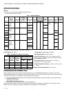
6. For regulator setpoint and spring range, please refer to
Table 3.
7. The low pressure regulator (V4944/V8944B,C,L,N) and
high pressure regulator V4943V8943B,C,N and
V4944/V8944B,C,L,N) adjustment screws (use a T-40
six-lobe [TORX®] driver or 5/16-in. standard driver) are
located under the slotted aluminum screw cap(s) of the
adjustment screw housings (see Fig. 1). To adjust the
pressure setting:
a. Temporarily remove the slotted aluminum screw cap
and gasket from the housing that contains the
regulator adjustment setscrew.
b. Turn the adjustment setscrew (use a T-40 six-lobe
[TORX®] driver or 5/16-in. standard driver) clockwise
to increase the pressure setting or counterclockwise
to decrease the pressure setting. Allow adequate time
(30 to 60 seconds) for the pressure to reach
equilibrium between pressure adjustments.
c. After the regulators have been properly adjusted,
replace the gasket and slotted aluminum screw cap
on the adjustment screw housing.
8. Start the system and observe its operation through at
least one complete cycle to make sure the valve
functions properly.
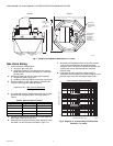
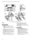
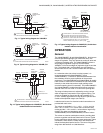
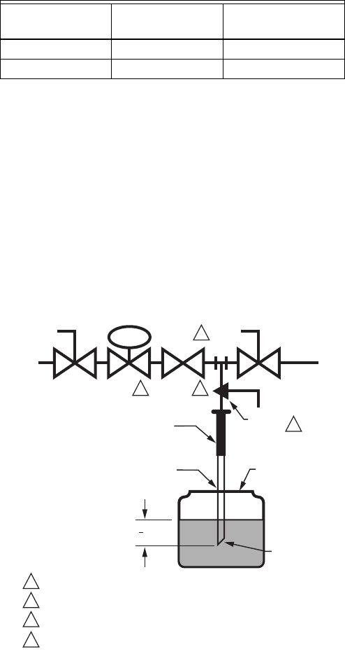
Valve Leak Test (See Fig. 15).
This test checks the tightness closure of a gas safety shutoff
valve. It should be performed by a qualified technician during
the initial startup of a burner system, or whenever the valve is
replaced (see Service Information section). It is recommended
that this test also be included in scheduled inspection and
maintenance procedures.
1. De-energize the control system to make sure there is no
power to the safety shutoff valve (C) shown in Fig. 15.
2. Close the upstream manual gas cock (A).
3. Make sure the manual test petcock (F) is closed in the
leak test tap assembly (D).
4. Remove the leak test tap plug (valve outlet pressure tap
can be used as a test tap) and connect the test
apparatus to the leak test tap (D).
5. Close the downstream manual gas cock (E).
6. Open the upstream manual gas cock (A).
7. Run the safety shutoff valve (C) to its fully open position
(through the safety system); then immediately
de-energize the system to close the valve.
8. Immerse a 1/4 in. tube vertically 1/2 in. (13 mm) into a jar
of water.
9. Slowly open the test petcock (F).
10. When the rate of bubbles coming through the water
stabilizes, count the number of bubbles appearing during
a ten-second period. Each bubble appearing during a
ten-second period represents a flow rate of
approximately 0.001 cfh.
To meet code requirements, leakage must not exceed the
values in Table 5.
Table 5. Allowable Leakage Rates.
a
Based on air standard conditions, test pressures in
accordance with ANSI Z21.21, Section 2.4.2 and a maximum
of 235 cc/h per inch of seal-off-diameter. Seal-off diameter is
not the same as pipe size.
11. Close the upstream manual gas cock (A).
12. Close the test petcock (F), remove the test apparatus,
and replace the leak test tap plug (D).
13. Open the upstream manual gas cock (A) and energize
the safety shutoff valve (C).
14. Test with soap bubbles to make sure there is no leak at
the test tap (D).
15. De-energize the safety shutoff valve (C).
16. Open the downstream manual gas cock (E).
17. Restore the system to normal operation.
Fig. 15. Valve leak test.
Pipe Size
(in.)
Allowable
a
Leakage
Number of Bubbles
per 10 sec.
1, 1-1/4 353 11 (Nat. gas), 7 (LP)
1-1/2, 2 453 14 (Nat. gas), 9 (LP)
M9547F
GAS
SUPPLY
UPSTREAM
MANUAL
GAS COCK
DOWNSTREAM
MANUAL
GAS COCK
BURNER
DABC E
F
PRV
MANUAL
TEST
PETCOCK
SSOV
1/4 IN. (6 MM)
FLEXIBLE
TUBING
1/4 IN. (6 MM)
ALUMINUM OR
COPPER PILOT
TUBING
JAR OR GLASS
WITH WATER
CUT AT
45 DEGREE
ANGLE
CAN ALSO BE A PERMANENT PETCOCK.
PRV = PRESSURE REGULATING VALVE.
SSOV = SAFETY SHUTOFF VALVE.
USE ONLY ONE OF THE DOWNSTREAM TAPS ON THE SS0V.
1
2
3
4
4
2 3
1
1
2
(13 MM)
LEAK
TEST
TAP