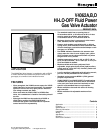
V4062A,B,D HI-LO-OFF FLUID POWER GAS VALVE ACTUATOR
60-2099—87
Recommended Procedure
To adjust the low-fire setting without energizing the actuator,
proceed as follows:
1. Remove the wiring compartment cover.
2. Manually rotate the cam and dial assembly downward
so that the setscrew is accessible from the front of the
actuator.
3. Loosen the setscrew on the low-fire cam using the
special wrench (supplied taped to the inside of the
actuator cover).
4. Set the cam to the predetermined low-fire setting for
the burner being used.
5. Tighten the setscrew in the cam.
6. Replace the wiring compartment cover.
Alternate Procedure
To adjust the low-fire setting after the burner is in operation,
use the following instructions:
1. Remove the wiring compartment cover.
2. Check to be sure the low-fire adjustment is set at MAX
to assure a safe lightoff. (Low-fire adjustment is preset
at the factory in the MAX position.)
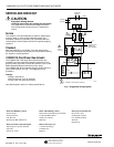
3. Disconnect the firing rate controller leadwire from
terminal 4 on the actuator to keep the valve in the low-
fire position (Fig. 4).
4. Start the system and establish the main burner flame.
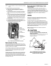
5. Loosen the setscrew in the cam (Fig. 5) with the
special wrench. Keep the wrench seated in the
setscrew. Rotate the cam slightly downward (by
moving the wrench toward the actuator base) to open
the bleed valve. The actuator will start to close.
6. When the valve reaches the desired low-fire position,
quickly tighten the setscrew and remove the wrench. If
the desired low-fire setting is missed, loosen the
setscrew and rotate the cam in the opposite direction
to the desired setpoint.
7. Shut down the burner, and then restart. Repeat several
times to be sure the low-fire setting is suitable for
correct burner lightoff. Readjust, if necessary.
8. Disconnect power and reconnect the controller
leadwire removed in step 3.
9. Replace the wiring compartment cover.
Adjust Auxiliary Switch (If Used)
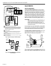
The auxiliary switch can be adjusted to operate at any point
in the actuator stroke. After installing the switch in the
actuator, turn the adjustment screw (Fig. 2) clockwise
to cause the switch to operate earlier in the stroke or turn
counterclockwise to cause the switch to operate later
in the stroke.
NOTE: The proof-of-closure switch is not adjustable.
Adjust Max Flow Limit Switch (Fig. 2)
The Max Flow Limit Switch is adjustable throughout the
actuator stroke. With the switch installed in the actuator, turn
the adjusting screw clockwise to cause the switch to
operate earlier in the stroke (less flow) or counterclockwise
to cause the switch to operate later in the stroke (more flow).
OPERATION
To function as intended, the V4062 must be connected to a
properly sized valve. Too large a valve will not properly
control the gas flow.
When the actuator is energized, it drives to the adjustable
low-fire position. Depending on the demand of the controller,
the valve remains at low-fire or moves to the high-fire
position. When the firing rate controller calls for no heat, the
actuator returns the valve to the low-fire position. When
power to the actuator is interrupted, the valve completely
closes.
Fig. 4 shows the V4062 in a typical flame safeguard control
system.


